مجموعة تكنولاب البهاء جروب
هل تريد التفاعل مع هذه المساهمة؟ كل ما عليك هو إنشاء حساب جديد ببضع خطوات أو تسجيل الدخول للمتابعة.

مجموعة تكنولاب البهاء جروب

تحاليل وتنقية ومعالجة المياه
 
الرئيسيةالبوابةأحدث الصورالتسجيلدخول
تنظيف وتطهير وغسيل واعادة تاهيل الخزانات


معمل تكنولاب البهاء جروب
 للتحاليل الكيميائية والطبية
والتشخيص بالنظائر المشعة
 للمخدرات والهرمونات والسموم
 وتحاليل المياه

مجموعة
تكنولاب البهاء جروب
لتصميم محطات الصرف الصناعى والصحى
لمعالجة مياه الصرف الصناعى والصحى
مجموعة تكنولاب البهاء جروب
المكتب الاستشارى العلمى
دراسات علمية كيميائية


معالجة الغلايات وانظمة البخار المكثف
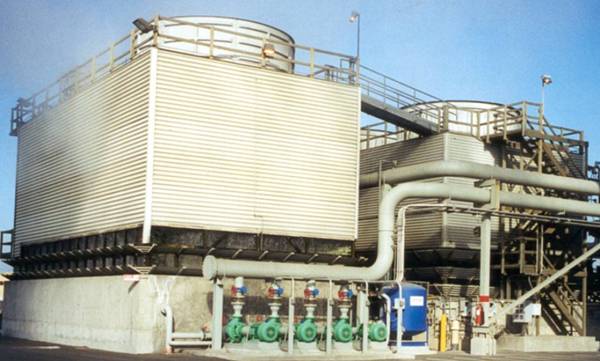
معالجة ابراج التبريد المفتوحة
معالجة الشيللرات
مجموعة تكنولاب البهاء جروب
اسنشاريين
كيميائيين/طبيين/بكترولوجيين
عقيد دكتور
بهاء بدر الدين محمود
رئيس مجلس الادارة
استشاريون متخصصون فى مجال تحاليل وتنقية ومعالجة المياه
متخصصون فى تصنيع وتصميم كيماويات
معالجة الصرف الصناعى والصحى
حسب كل مشكلة كل على حدة
تصنيع وتحضير كيماويات معالجة المياه الصناعية
مؤتمرات/اجتماعات/محاضرات/فريق عمل متميز
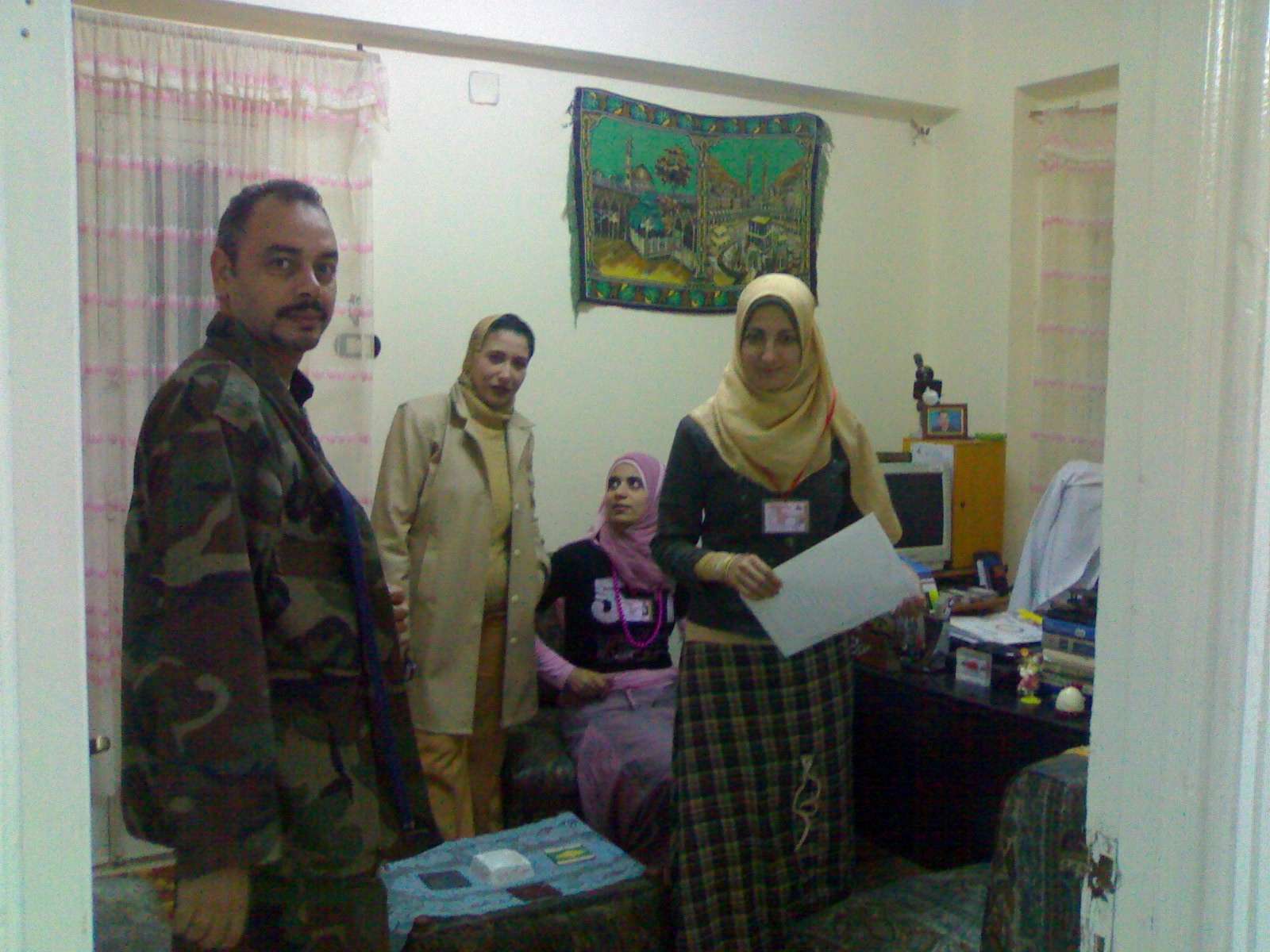
صور من وحدات معالجة المياه


technolab el-bahaa group
TECHNOLAB EL-BAHAA GROUP
EGYPT
FOR
WATER
TREATMENT/PURIFICATION/ANALYSIS
CONSULTANTS
CHEMIST/PHYSICS/MICROBIOLIGIST
 
INDUSTRIAL WATER
WASTE WATER
DRINKING WATER
TANKS CLEANING
 
CHAIRMAN
COLONEL.DR
BAHAA BADR EL-DIN
0117156569
0129834104
0163793775
0174041455


تصميم وانشاء محطات صرف صناعى/waste water treatment plant design

technolab el-bahaa group
egypt
We are a consultants in water treatment with our chemicals as:-
Boiler water treatment chemicals
Condensated steam treatment chemicals
Oxygen scavenger treatment chemicals
Ph-adjustment treatment chemicals
Antiscale treatment chemicals
Anticorrosion treatment chemicals
Open cooling tower treatment chemicals
Chillers treatment chemicals
Waste water treatment chemicals
Drinking water purification chemicals
Swimming pool treatment chemicals
Fuel oil improver(mazote/solar/benzene)
technolab el-bahaa group
egypt
We are consultants in extraction ,analysis and trading the raw materials of mines as:-
Rock phosphate
32%-30%-28%-25%
Kaolin
Quartez-silica
Talcum
Feldspae(potash-sodumic)
Silica sand
Silica fume
Iron oxid ore
Manganese oxid
Cement(42.5%-32.5%)
Ferro manganese
Ferro manganese high carbon


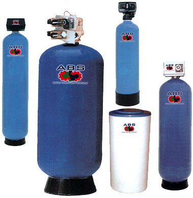
water treatment unit design


وكلاء لشركات تركية وصينية لتوريد وتركيب وصيانة الغلايات وملحقاتها
solo agent for turkish and chinese companies for boiler production/manufacture/maintance


وكلاء لشركات تركية وصينية واوروبية لتصنيع وتركيب وصيانة ابراج التبريد المفتوحة


تصميم وتوريد وتركيب الشيللرات
design/production/maintance
chillers
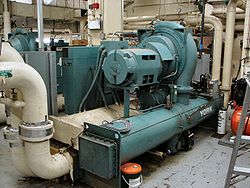
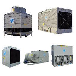
ابراج التبريد المفتوحة
مجموعة تكنولاب البهاء جروب
المكتب الاستشارى العلمى
قطاع توريد خطوط انتاج المصانع
 
نحن طريقك لاختيار افضل خطوط الانتاج لمصنعكم
سابقة خبرتنا فى اختيار خطوط الانتاج لعملاؤنا
 
1)خطوط انتاج العصائر الطبيعية والمحفوظة والمربات
2)خطوط انتاج الزيوت الطبيعية والمحفوظة
3)خطوط انتاج اللبن الطبيعى والمحفوظ والمبستر والمجفف والبودرة
4)خطوط تعليب وتغليف الفاكهة والخضروات
5)خطوط انتاج المواسير البلاستيك والبى فى سى والبولى ايثيلين
6)خطوط انتاج التراى كالسيوم فوسفات والحبر الاسود
7)خطوط انتاج الاسفلت بانواعه
Coolمحطات معالجة الصرف الصناعى والصحى بالطرق البيولوجية والكيميائية
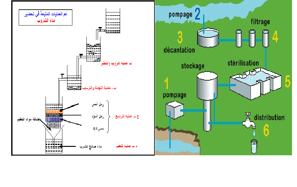
9)محطات معالجة وتنقية مياه الشرب
10)محطات ازالة ملوحة البحار لاستخدامها فى الشرب والرى
11)الغلايات وخطوط انتاج البخار الساخن المكثف
12)الشيللرات وابراج التبريد المفتوحة وخطوط انتاج البخار البارد المكثف
 
للاستعلام
مجموعة تكنولاب البهاء جروب
0117156569
0129834104
0163793775
 
القاهرة-شارع صلاح سالم-عمارات العبور-عمارة 17 ب
فلا تر رملية/كربونية/زلطيه/حديدية
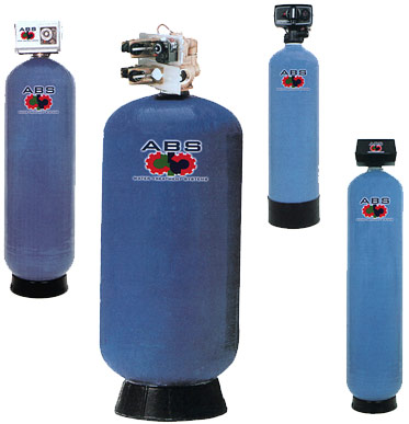
وحدات سوفتنر لازالة عسر المياه
مواصفات مياه الشرب
Drinking water
acceptable
values

50

colour

acceptable

Taste

nil

Odour

6.5-9.2

ph


1 mg/dl

pb

5 mg/dl

as

50 mg/dl

cn

10 mg/dl

cd

0-100mg/dl

hg

8 mg/dl

f

45 mg/dl

N02

1 mg/dl

Fe

5 mg/dl

Mn

5.1 mg/dl

Cu

200 mg/dl

Ca

150 mg/dl

Mg

600 mg/dl

Cl

400 mg/dl

S04

200 mg/dl

Phenol

15 mg/dl

zn


الحدود المسموح به
ا لملوثات الصرف الصناعى
 بعد المعالجة
Acceptable
values
treated wate water
7-9.5

ph

25-37 c

Temp

40 mg/dl

Suspended solid

35 mg/dl

bod

3 mg/dl

Oil & grase

0.1 mg/dl

hg

0.02 mg/dl

cd

0.1 mg/dl

cn

0.5mg/dl

phenol

1.5 ds/m

conductivity

200 mg/dl

na

120 mg/dl

ca

56 mg/dl

mg

30 mg/dl

k

200 mg/dl

cl

150 mg/dl

S02

0.75 mg/dl

Fe

0.2 mg/dl

Zn

0.5 mg/dl

Cu

0.03 mg/dl

Ni

0.09 mg/dl

Cr

0.53 mg/dl

لb

0.15 mg/dl

pb


pipe flocculator+daf
plug flow flocculator
lamella settels

محطات تحلية مياه البحر بطريقة التقطير الومضى على مراحل
MSF+3.jpg (image)
محطات التقطير الومضى لتحلية مياه البحر2[MSF+3.jpg]
some of types of tanks we services
انواع الخزانات التى يتم تنظيفها
ASME Specification Tanks
Fuel Tanks
Storage Tanks
Custom Tanks
Plastic Tanks
Tank Cleaning Equipment
Double Wall Tanks
Septic Tanks
Water Storage Tanks
Fiberglass Reinforced Plastic Tanks
Stainless Steel Tanks
Custom / Septic
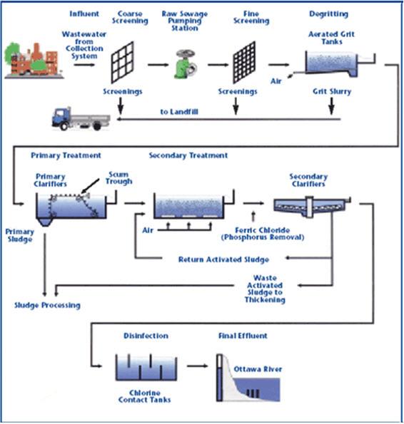
مراحل المعالجة الاولية والثانوية والمتقدمة للصرف الصناعى

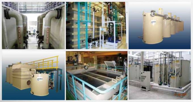
صور مختلفة
من وحدات وخزانات معالجة الصرف الصناعى
 التى تم تصميمها وتركيبها من قبل المجموعة
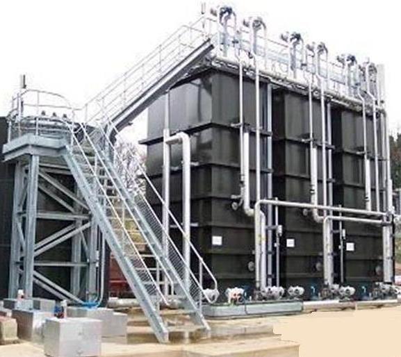
صور
 من خزانات الترسيب الكيميائى والفيزيائى
 لوحدات معالجة الصرف الصناعى
المصممة من قبل المحموعة


technolab el-bahaa group


technolab el-bahaa group


technolab el-bahaa group

technolab el-bahaa group


technolab el-bahaa group


technolab el-bahaa group


technolab el-bahaa group


technolab el-bahaa group


technolab el-bahaa group


technolab el-bahaa group


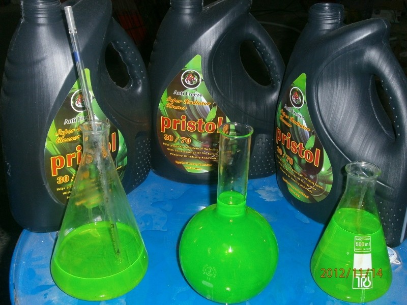
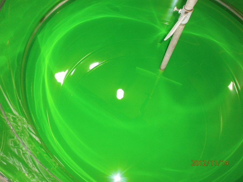
مياه رادياتير اخضر اللون
بريستول تو ايه
انتاج شركة بريستول تو ايه - دمياط الجديدة
مجموعة تكنولاب البهاء جروب

اسطمبات عبوات منتجات شركة بريستول تو ايه-دمياط الجديدة
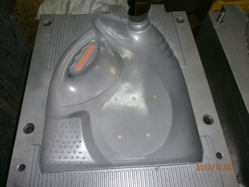
مياه رادياتير خضراء فوسفورية

من انتاج شركة بريستول تو ايه 

بترخيص من مجموعة تكنولاب البهاء جروب


زيت فرامل وباكم

DOT3


 التصميم العام لمنظومة حقن الكلور فى المياه

اذهب الى الأسفل 
كاتب الموضوعرسالة
Admin
Admin
Admin


عدد المساهمات : 3762
تاريخ التسجيل : 15/09/2009
العمر : 57
الموقع : مصر

التصميم العام لمنظومة حقن الكلور فى المياه Empty
مُساهمةموضوع: التصميم العام لمنظومة حقن الكلور فى المياه   التصميم العام لمنظومة حقن الكلور فى المياه Emptyالخميس فبراير 14, 2013 2:24 pm

1
GENERAL GAS CHLORINE DESIGN

The design of gas chlorine facilities should consider operator and public safety as well as
maintaining long-term plant reliability and operation.

Chlorination facilities shall be designed
such that chlorine gas can be contained in the chlorine storage room.

Doors and windows
should be gas-tight to minimize escape of gaseous chlorine to the exterior atmosphere or building
interior.

In general, the following can be considered to be acceptable design:

1. All chlorine cylinders shall be contained in the chlorine storage room.

Vacuum
regulators should be located on individual chlorine cylinders in service.

The use of
pressurized chlorine gas lines and manifolds is strongly discouraged and, if utilized, must
be contained in the chlorine storage room.

2.

All chlorine cylinders shall be adequately restrained.

3.

Chlorinators should be housed in a room separate from but adjacent to the chlorine
storage room.

This is to minimize the need to enter the storage room to adjust feed rates
and to minimize the potential for equipment damage caused by chlorine leaks.

A gastight shatter resistant window shall be present for viewing the storage and chlorinator
rooms from an interior wall of the plant.

4. The chlorine storage room shall only be accessible from the outside.

The exterior access
door for the chlorine storage area must open outward, being equipped with panic bar
hardware on the interior.

A small viewing window should be present in the door or
adjacent to the door in the exterior wall to allow operator examination of the room before
entry.

Loading dock doors shall also open outward and be equipped with the appropriate
moldings, gaskets, and weather stripping to minimize gas leakage to the exterior.

Inside
access to the chlorinator room shall be acceptable if chlorine gas is supplied under
vacuum.

5.

All access doors should be properly labeled with appropriate warning signs.

6.

Chlorinator room temperature should be maintained at 60 degrees Fahrenheit and
protected from excessive heat.

The chlorine storage room shall be maintained at a
temperature 5 to 10 degrees Fahrenheit cooler than the chlorinator room to minimize the
potential for re-liquification of the gas.

7.

A pressure relief valve shall be located on the chlorine vacuum line within the vacuum
regulator to prevent gas pressurization of the chlorinator.

This valve should be vented to
the chlorine storage room or to the outside if appropriate.

8.

All openings between the chlorine storage room and other parts of the building shall be
sealed such that chlorine leaks can be contained within the storage room.

9.

There shall be no exterior windows to chlorine storage rooms other than the small
viewing window at the entrance.

(This is to minimize the potential for heat build-up from
the sun and to minimize vandalism.)

10.

Scales shall be constructed of durable material to withstand the aggressive environment
and situated such that they can be easily and accurately read through a viewing window
or use of a remote readout.

This type of design will minimize the need to enter the
chlorine storage area to take readings.

11.

Separate light and ventilation switches shall be located outside of the chlorine storage
room near the entrance door and interior viewing window.

Lighting fixtures within the
chlorine storage area shall be suitable for use in an aggressive environment and, if
possible, designed to operate during a chlorine gas release.


12.

Electrical components within the chlorine storage area should be minimized.

Motors for
louvers, cylinder cranes, and ventilation equipment shall be suitable for use in an
aggressive environment.

Convenience electrical components, such as outlets, should be
avoided.

All electrical systems for the chlorine storage area shall be on dedicated
circuits.

13.

The chlorine storage room shall be equipped with ventilation equipment capable of one
complete air exchange per minute.

This equipment shall be located such that it will draw
suction near the floor as far away as practical from the entrance door and air inlet.

Exhaust shall be located away from the door and other air intakes.

Exhaust discharge
shall be located as not to contaminate other air inlets to any rooms or structures.

Air
intakes should be through louvers near the ceiling.

Louvers for intakes and exhaust shall
facilitate airtight closure.

14.

Chemical scrubbing systems should be considered for treating the exhaust from a
chlorine release where such exhaust may otherwise represent a health or environmental
hazard to the surrounding area.

15.

All ventilation and duct work within a chlorine storage room shall be separated from
domestic building ventilation systems.

All chlorine room duct work should be gas tight
and not pass through other rooms or areas of the building.

16.

Leak detectors shall be located 1 foot above the floor of the chlorine storage room and
shall activate an alarm when a chlorine leak occurs.

It is preferable that the detector be
capable of differentiating between two or more chlorine concentrations to alert personnel
of the severity of the release.

This would help determine the appropriate procedure for
entrance to the room, ventilation, or other solutions.

17.

Self contained breathing apparatus (SCBA) shall not be located within the chlorine
storage room.

It is preferable that this equipment be located in a convenient location
where personnel can easily access it in the event of an emergency.

18.

Service water to operator injectors/eductors shall be of adequate supply and pressure to
operate feed equipment within the needed chlorine dosage range for the proposed system.

All service water shall be properly protected by the appropriate cross connection control
device.

19.

Placement of injectors/eductors should be carefully evaluated.

Current system operation
and chlorination practices should also be reviewed before design.

In some cases, it may
be appropriate to locate the injector/eductor in the chlorinator room with distribution of
highly chlorinated water to the point of application.

In other situations, it may be best to
locate the eductor/injector can at the point of application with distribution of chlorine gas
through plastic tubing under vacuum to the point of application.

20.

A chlorine cylinder repair kit with leak detection bottle should be supplied within each
chlorine storage room.

21.

Floor drains should not be designed within the chlorine storage area.

22.

Combustible materials should not be stored in chlorine rooms.

23.

Fire sprinkling systems should not be installed in chlorine rooms.

24.

Chlorine room location should be on the prevailing downwind side of the building, away
from entrances, windows, louvers, walkways, etc.

25.

Ammonia storage shall be in rooms separate from the chlorine storage room.
الرجوع الى أعلى الصفحة اذهب الى الأسفل
https://technolabelbahaagp.yoo7.com
Admin
Admin
Admin


عدد المساهمات : 3762
تاريخ التسجيل : 15/09/2009
العمر : 57
الموقع : مصر

التصميم العام لمنظومة حقن الكلور فى المياه Empty
مُساهمةموضوع: رد: التصميم العام لمنظومة حقن الكلور فى المياه   التصميم العام لمنظومة حقن الكلور فى المياه Emptyالخميس فبراير 14, 2013 2:45 pm

[img]التصميم العام لمنظومة حقن الكلور فى المياه 2012-010[/img]

[img]التصميم العام لمنظومة حقن الكلور فى المياه 2012-011[/img]

[img]التصميم العام لمنظومة حقن الكلور فى المياه 2012-012[/img]

[img]التصميم العام لمنظومة حقن الكلور فى المياه 2012-013[/img]

[img]التصميم العام لمنظومة حقن الكلور فى المياه 2012-014[/img]

[img]التصميم العام لمنظومة حقن الكلور فى المياه 2012-015[/img]
الرجوع الى أعلى الصفحة اذهب الى الأسفل
https://technolabelbahaagp.yoo7.com
 
التصميم العام لمنظومة حقن الكلور فى المياه
الرجوع الى أعلى الصفحة 
صفحة 1 من اصل 1

صلاحيات هذا المنتدى:لاتستطيع الرد على المواضيع في هذا المنتدى
مجموعة تكنولاب البهاء جروب :: قسم معالجة وتنقية وتحاليل المياه :: تصميم وتركيب وتوريد وحدات معالجة المياه-
انتقل الى: