 مجموعة تكنولاب البهاء جروب تحاليل وتنقية ومعالجة المياه |
 |
تنظيف وتطهير وغسيل واعادة تاهيل الخزانات  معمل تكنولاب البهاء جروب للتحاليل الكيميائية والطبية والتشخيص بالنظائر المشعة للمخدرات والهرمونات والسموم وتحاليل المياه  مجموعة
تكنولاب البهاء جروب
لتصميم محطات الصرف الصناعى والصحى
لمعالجة مياه الصرف الصناعى والصحى
 مجموعة تكنولاب البهاء جروب
المكتب الاستشارى العلمى
دراسات علمية كيميائية
 معالجة الغلايات وانظمة البخار المكثف
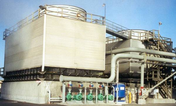
معالجة ابراج التبريد المفتوحة
معالجة الشيللرات
 مجموعة تكنولاب البهاء جروب
اسنشاريين
كيميائيين/طبيين/بكترولوجيين
عقيد دكتور
بهاء بدر الدين محمود
رئيس مجلس الادارة
 استشاريون متخصصون فى مجال تحاليل وتنقية ومعالجة المياه
   متخصصون فى تصنيع وتصميم كيماويات
معالجة الصرف الصناعى والصحى
حسب كل مشكلة كل على حدة تصنيع وتحضير كيماويات معالجة المياه الصناعية
 مؤتمرات/اجتماعات/محاضرات/فريق عمل متميز 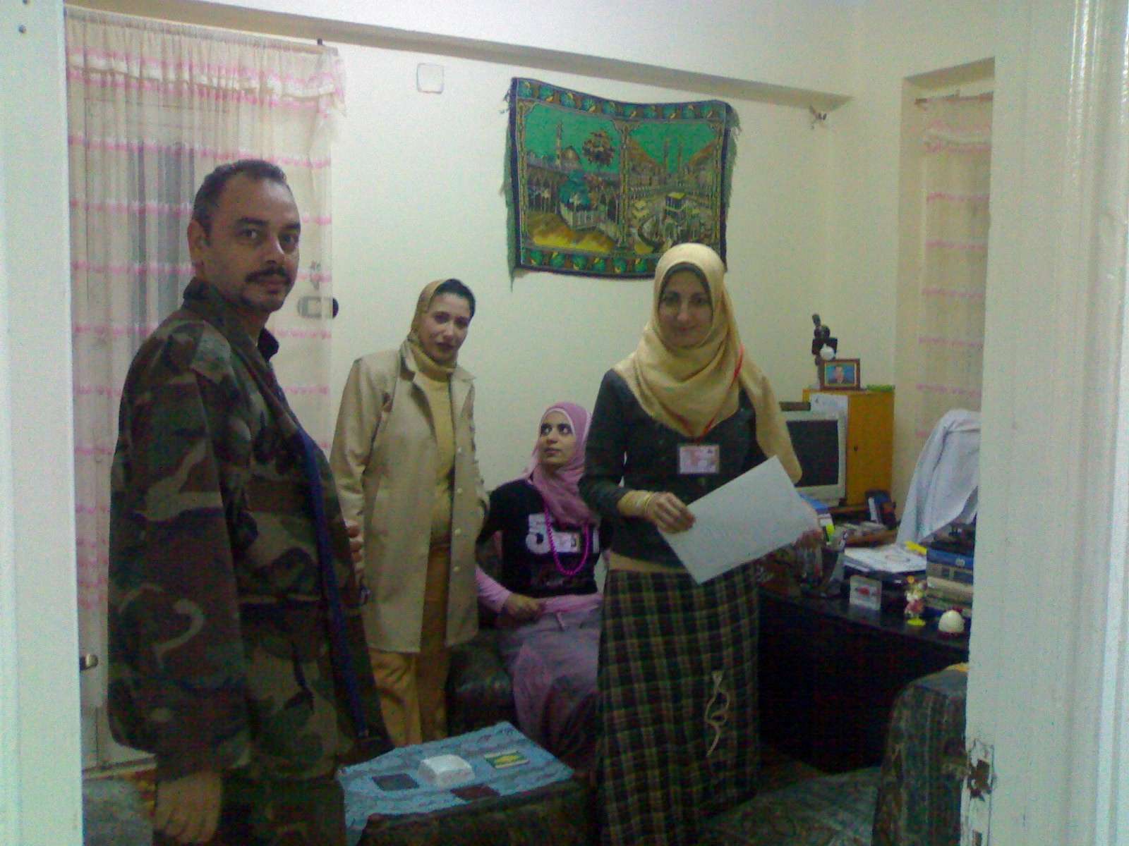 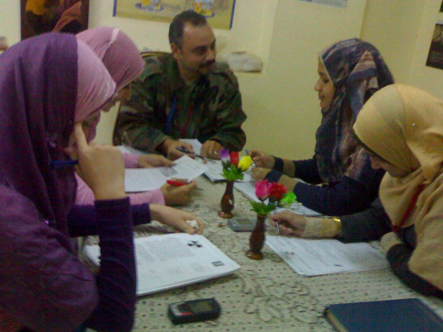    صور من وحدات معالجة المياه
  technolab el-bahaa group  TECHNOLAB EL-BAHAA GROUP
EGYPT
FOR
WATER
TREATMENT/PURIFICATION/ANALYSIS
CONSULTANTS
CHEMIST/PHYSICS/MICROBIOLIGIST
INDUSTRIAL WATER
WASTE WATER
DRINKING WATER
TANKS CLEANING
CHAIRMAN
COLONEL.DR
BAHAA BADR EL-DIN
0117156569
0129834104
0163793775
0174041455
تصميم وانشاء محطات صرف صناعى/waste water treatment plant design  technolab el-bahaa group egypt We are a consultants in water treatment with our chemicals as:- Boiler water treatment chemicals Condensated steam treatment chemicals Oxygen scavenger treatment chemicals Ph-adjustment treatment chemicals Antiscale treatment chemicals Anticorrosion treatment chemicals Open cooling tower treatment chemicals Chillers treatment chemicals Waste water treatment chemicals Drinking water purification chemicals Swimming pool treatment chemicals Fuel oil improver(mazote/solar/benzene) technolab el-bahaa group
egypt
We are consultants in extraction ,analysis and trading the raw materials of mines as:-
Rock phosphate
32%-30%-28%-25%
Kaolin
Quartez-silica
Talcum
Feldspae(potash-sodumic)
Silica sand
Silica fume
Iron oxid ore
Manganese oxid
Cement(42.5%-32.5%)
Ferro manganese
Ferro manganese high carbon technolab el-bahaa group
web sites
e-mails
 water treatment unit design 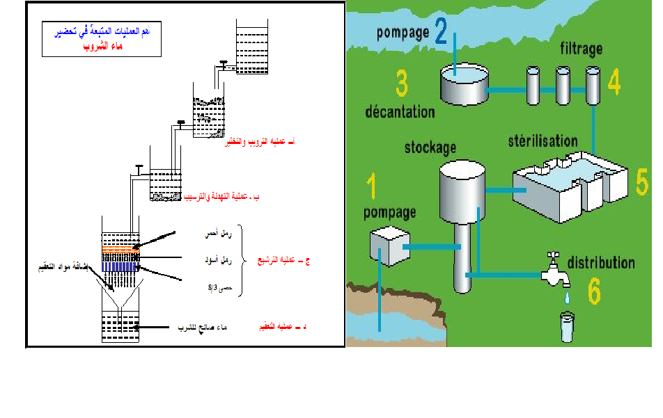       
وكلاء لشركات تركية وصينية لتوريد وتركيب وصيانة الغلايات وملحقاتها
solo agent for turkish and chinese companies for boiler production/manufacture/maintance 
وكلاء لشركات تركية وصينية واوروبية لتصنيع وتركيب وصيانة ابراج التبريد المفتوحة
تصميم وتوريد وتركيب الشيللرات
design/production/maintance
chillers 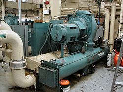 ابراج التبريد المفتوحة 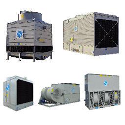 مجموعة تكنولاب البهاء جروب
المكتب الاستشارى العلمى
قطاع توريد خطوط انتاج المصانع
نحن طريقك لاختيار افضل خطوط الانتاج لمصنعكم
سابقة خبرتنا فى اختيار خطوط الانتاج لعملاؤنا
1)خطوط انتاج العصائر الطبيعية والمحفوظة والمربات
2)خطوط انتاج الزيوت الطبيعية والمحفوظة
3)خطوط انتاج اللبن الطبيعى والمحفوظ والمبستر والمجفف والبودرة
4)خطوط تعليب وتغليف الفاكهة والخضروات
5)خطوط انتاج المواسير البلاستيك والبى فى سى والبولى ايثيلين
6)خطوط انتاج التراى كالسيوم فوسفات والحبر الاسود
7)خطوط انتاج الاسفلت بانواعه
9)محطات معالجة وتنقية مياه الشرب
10)محطات ازالة ملوحة البحار لاستخدامها فى الشرب والرى
11)الغلايات وخطوط انتاج البخار الساخن المكثف
12)الشيللرات وابراج التبريد المفتوحة وخطوط انتاج البخار البارد المكثف
للاستعلام
مجموعة تكنولاب البهاء جروب
0117156569
0129834104
0163793775
القاهرة-شارع صلاح سالم-عمارات العبور-عمارة 17 ب فلا تر رملية/كربونية/زلطيه/حديدية 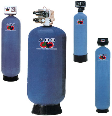 وحدات سوفتنر لازالة عسر المياه 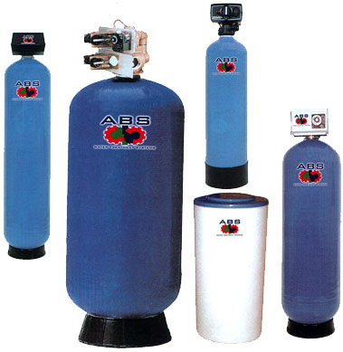 مواصفات مياه الشرب
Drinking water
acceptable
values
الحدود المسموح به
ا لملوثات الصرف الصناعى
بعد المعالجة
Acceptable
values
treated wate water
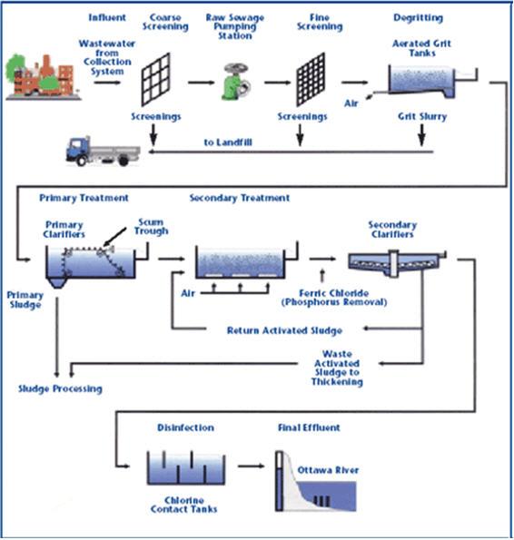
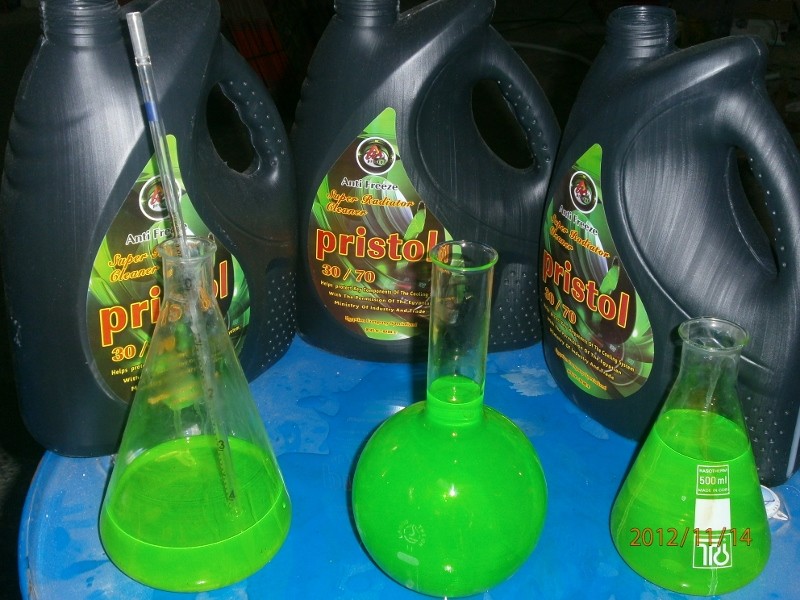
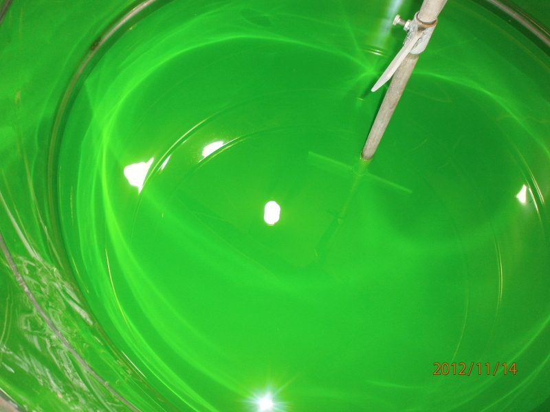
    pipe flocculator+daf plug flow flocculator lamella settels محطات تحلية مياه البحر بطريقة التقطير الومضى على مراحل  محطات التقطير الومضى لتحلية مياه البحر2 ![[MSF+3.jpg]](https://2img.net/h/4.bp.blogspot.com/_SynCnHGx75g/Shl2T3oVhsI/AAAAAAAAAEY/_7oem5pvQ3I/s1600/MSF%2B3.jpg) some of types of tanks we services انواع الخزانات التى يتم تنظيفها ASME Specification TanksFuel Tanks Storage Tanks Custom Tanks Plastic Tanks Tank Cleaning Equipment Double Wall Tanks Septic Tanks Water Storage Tanks Fiberglass Reinforced Plastic Tanks Stainless Steel Tanks Custom / Septic مراحل المعالجة الاولية والثانوية والمتقدمة للصرف الصناعى  صور مختلفة من وحدات وخزانات معالجة الصرف الصناعى التى تم تصميمها وتركيبها من قبل المجموعة 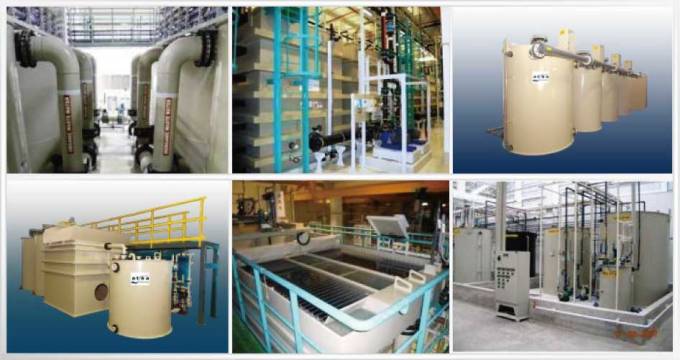 صور من خزانات الترسيب الكيميائى والفيزيائى لوحدات معالجة الصرف الصناعى المصممة من قبل المحموعة 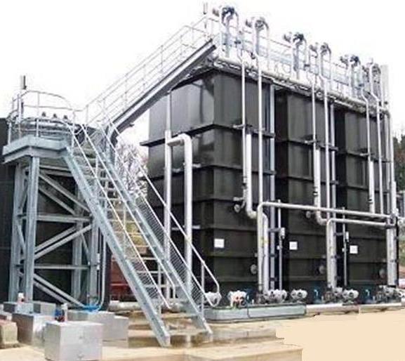  technolab el-bahaa group  technolab el-bahaa group  technolab el-bahaa group  technolab el-bahaa group  technolab el-bahaa group  technolab el-bahaa group  technolab el-bahaa group  technolab el-bahaa group  technolab el-bahaa group  technolab el-bahaa group      مياه رادياتير اخضر اللون بريستول تو ايه انتاج شركة بريستول تو ايه - دمياط الجديدة مجموعة تكنولاب البهاء جروب 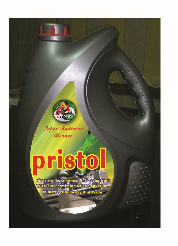         اسطمبات عبوات منتجات شركة بريستول تو ايه-دمياط الجديدة 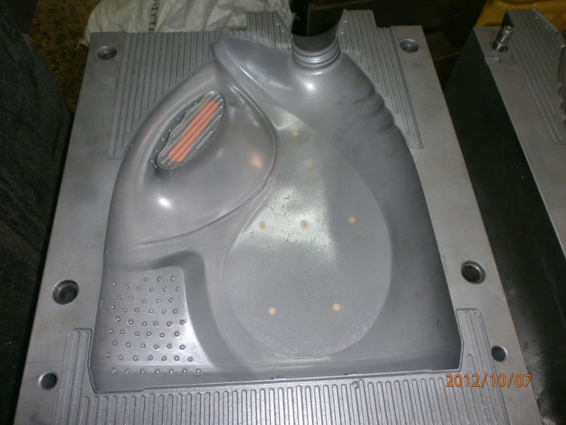  مياه رادياتير خضراء فوسفورية من انتاج شركة بريستول تو ايه بترخيص من مجموعة تكنولاب البهاء جروب
 |


|


