|
| | دراسة جدوى فنية تصميمية انشاء مصنع انتاج الصودا الكاوية القشور 99% والسائلة 48% فى مصر |  |
| | |
| كاتب الموضوع | رسالة |
|---|
Admin
Admin

عدد المساهمات : 3762
تاريخ التسجيل : 15/09/2009
العمر : 57
الموقع : مصر
 |  موضوع: دراسة جدوى فنية تصميمية انشاء مصنع انتاج الصودا الكاوية القشور 99% والسائلة 48% فى مصر موضوع: دراسة جدوى فنية تصميمية انشاء مصنع انتاج الصودا الكاوية القشور 99% والسائلة 48% فى مصر  الثلاثاء نوفمبر 20, 2018 12:57 pm الثلاثاء نوفمبر 20, 2018 12:57 pm | |
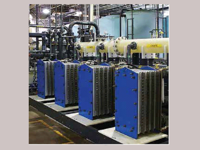
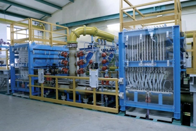
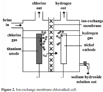
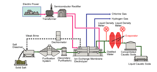
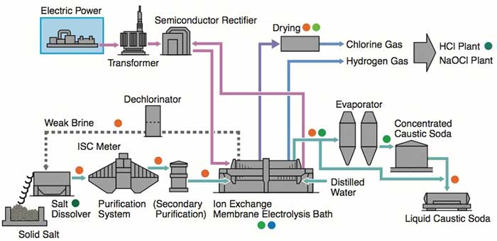
| مقدمة علميةCAUSTIC SODA PRODUCTION LINE LIQUID & FLAKES 1.General Outline The plant is designed to produce close to 100 TDP of caustic soda by Ion Exchange Membrane electrolysis process. This process has replaced the Mercury Cell process as it produced huge amounts of mercury as waste,which was highly toxic to the environment. Chlorine and Hydrogen gases are liberated as side products. The raw materials are raw salt, water and power. The final products are a ) 32.5 wt% caustic soda (concentrated to 48% in existing mercury cell) b)liquid chlorine c)hydrogen gas The plant consists of sections for raw material treatment, electrolysis, product treatment and utility supply. The chemical process, however, may be broadly classified into three sections: section (1) Brine treatment a)Primary brine precipitation and chemical preparation b)Primary brine filtration c)Sludge treatment d)Secondary brine purification e)Brine dechlorination section(2) Electrolysis (32% caustic, H2, Cl2 as products) Section (3) Caustic concentration a)Caustic Evaporation Plant (32% caustic to 48% caustic lye) b)Fusion Plant (48% caustic lye to 98% caustic flakes) | |
|   | | Admin
Admin

عدد المساهمات : 3762
تاريخ التسجيل : 15/09/2009
العمر : 57
الموقع : مصر
 |  موضوع: رد: دراسة جدوى فنية تصميمية انشاء مصنع انتاج الصودا الكاوية القشور 99% والسائلة 48% فى مصر موضوع: رد: دراسة جدوى فنية تصميمية انشاء مصنع انتاج الصودا الكاوية القشور 99% والسائلة 48% فى مصر  الثلاثاء نوفمبر 20, 2018 1:01 pm الثلاثاء نوفمبر 20, 2018 1:01 pm | |
| 2. Process description 2.1 Primary brine purification The depleted brine after vacuum de-chlorination and sodium sulfite treatment is sent to, the saturators. Two saturators are provided; one working and one stand by. However, when one is in service, a small quantity of depleted brine is sent through the other saturators to prevent clogging of dip pipe as well as to remove the impurities by leaching. During the electrolysis, some amount of water from brine will be transported to the cathode compartment along with the sodium ions. This water loss from brine is made up by adding DM water tom the depleted brine beforetit enters the saturators. The concentration of crude brine is controlled by mixing some amount of lean brine with saturated brine from the saturators inside a strainer tank. Raw salt contains many insoluble matters, which get settled at the bottom of the saturators. These insolubles are removed periodically from the bottom of saturator. The bottom discharge is collected in a saturator recovery pit. When the insolubles are settled, the clean brine is recovered back to the saturator by the raw salt sludge pump. The crude brine contains impurities like calcium, magnesium, sulphates, heavy metals etc. the calcium,magnesium and sulphates are eliminated by treating the crude brine with the sodium carbonate, sodium hydroxide and barium carbonate respectively. The reactions are carried out in two reactors. The sodium carbonate and barium carbonate are added to the first reactor and sodium hydroxide in the second rector. To speed up the reaction and to prevent settling of precipitators, both reactors are provided with agitation. The first reactor is agitated with air and the second one with mechanical agitator (since any air bubble trapped in the brine affects the settling efficiency of clarifier, in the second reactor air agitation is not used.). and 20 % NaOH supplied to the reactor are controlled to get an excess sodium hydroxide content of 150 – 200 mg p l and excess carbonate content of 250 – 300 mg p l in the brine at the out letof second reactor. Barium carbonate slurry concentration is kept at around 16 wt%. The brine recovered from various operations are collected in a pit and supplied to the first reactor at constant flow rate. For the stable operation of the clarifier, it is advisable not to allow major variations in the flow rate of recovered brine. Crude brine overflowing from the second reactor enters a flocculants mixing tank where 0.05 wt% flocculants solution so that the concentration of flocculants in brine is maintained at around 5 ppm. (This quantity may further be reduced as per the actual performance of the clarifier). The brine then over flows into the clarifier where the residence time is long. In the clarifier, all the reactions are completed and the precipitates get settled at the bottom. The precipitates are periodically removed from the bottom and sent to the vacuum drum filter using clarifier sludge pump. The clarifier is a water seal type, where a layer of water is always maintained on the surface of brine to prevent heat loss from brine due to radiation and to prevent convection current (thereby settling is improved). If the water layer decreases, the sealing water temperature increases. Then the clarifier is to be supplied with additional sealing water supply at the top. DM water is used as the sealing water. The clarifier brine overflows into the CB tank. The suspended solid of this brine is about 20 ppm or less. | |
|   | | Admin
Admin

عدد المساهمات : 3762
تاريخ التسجيل : 15/09/2009
العمر : 57
الموقع : مصر
 |  موضوع: رد: دراسة جدوى فنية تصميمية انشاء مصنع انتاج الصودا الكاوية القشور 99% والسائلة 48% فى مصر موضوع: رد: دراسة جدوى فنية تصميمية انشاء مصنع انتاج الصودا الكاوية القشور 99% والسائلة 48% فى مصر  الثلاثاء نوفمبر 20, 2018 1:04 pm الثلاثاء نوفمبر 20, 2018 1:04 pm | |
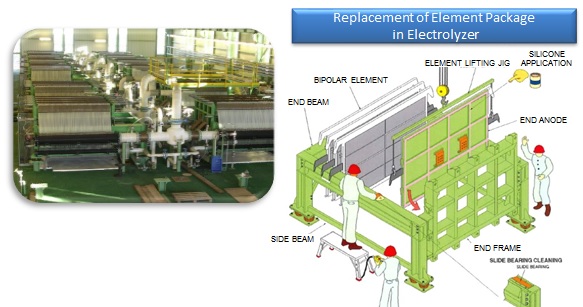
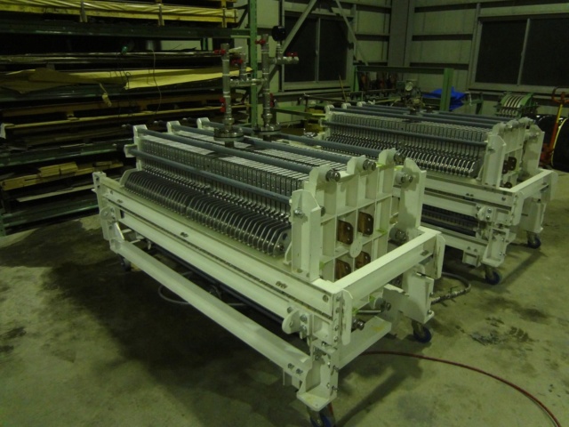
| SLUDGE FILTRATION AND BRINE RECOVERY 1. Clarifier underflows, precipitates underflow and the backwash from polishing filter are collected in the sludge pit. 2. The polishing filter backwash, clarifier underflow are filtered using vacuum filter and the filtrate is collected in recovered brine pits. 3. The backwash brine from Anthracite filters, various tank overflows and the filtrate from vacuum drum filter are collected in the recovered brine pits. 4. From the pit recovered brine is continuously fed to the brine circuit at a constant flow rate using recovered brine pumps. PROCESS DESCRIPTION 1Electrolyzer circuit The electrolyzer circuit has 44 no.s of DCM 405 x 2 electrolyzers and a rectifier unit. The circuit is arranged in two rows. Both rows are connected to the rectifier unit with power supply bars and one row is connected to the other with cross over bus bars at the opposite side of the rectifier unit. Each electrolyzer in a row is connected with each other through inter cell bus bars. 2Fluid stream (Super purified brine) Super purified brine from the brine treatment section is fed into the feed brine manifold of eachDCM 405 X 2 electrolyzer through a header pipe and each branch pipe. Brine is distributed to each anode chamber. A restriction orifice is provided at the inlet of each anode chamber respectively. Brine flow rate to each DCM 405 X 2 electrolyzer is adjusted by a brine flow gauge mounted on each branch pipe. 3Anode chamber Super purified brine fed into anode chamber is decomposed electrically into Cl- and Na+ by direct current in the anode chamber. The Cl- ions are oxidized at the anode surface and from chlorine gas. Depleted brine and wet chlorine gas at 80 – 90° C form a two phase system and overflow out of the anode chamber. The two phase flows from each anode chamber and are collected into the manifold of each electrolyzer and flows by gravity into depleted brine tank (V.201) from the depleted brine tank chlorine gas goes to chlorine gas treatment section and depleted brine pumped to brine treatment section. The sodium ions in the anode chamber pass through the membrane and enter into the cathode chamber together with water. Cathode chamber In the cathode chamber water is decomposed electrolytically into H+ and OH- by direct current. The H+ ions are reduced on the cathode surface and form Hydrogen gas. The OH- ions combinewith Na+ ions and form caustic soda. The two phase stream of NaOH + H2 at 80-90 Deg. Cover flows out of each cathode chamber and are collected into the manifold; they flow by gravity to NaOH circulation tank (V.202). From the NaOH circulation tank, Hydrogen gas and NaOH separated. Hydrogen gas goes to theHydrogen circulation pump (P.202 A/B). This caustic soda is separated into two streams. a)32.5 wt% caustic head tank for conc. In Mercury cell up to 48%. b)Recycle NaOH to the electrolyzer Recycled caustic is fed to the recycle caustic manifold of each DCM 405 X 2 electrolyzer through a header pipe and each branch pipe and distributed to each cathode chamber. Caustic flow gauge mounted on each branch pipe is used for adjusting the caustic flow rate to each electrolyzer . The caustic strength is generally kept about 32.5 wt% at the outlet of the electrolyzer by controlling feed quantity of DM water which is added into the recycle caustic stream. | |
|   | | Admin
Admin

عدد المساهمات : 3762
تاريخ التسجيل : 15/09/2009
العمر : 57
الموقع : مصر
 |  موضوع: رد: دراسة جدوى فنية تصميمية انشاء مصنع انتاج الصودا الكاوية القشور 99% والسائلة 48% فى مصر موضوع: رد: دراسة جدوى فنية تصميمية انشاء مصنع انتاج الصودا الكاوية القشور 99% والسائلة 48% فى مصر  الثلاثاء نوفمبر 20, 2018 1:07 pm الثلاثاء نوفمبر 20, 2018 1:07 pm | |
| CAUSTIC SODA HEAT EXCHANGER A caustic soda heat exchanger is installed in the recycled caustic steam to control electrolysis temperature by cooling down or by heating up. This heat exchanger functions as a heater to warm up the electrolyte in the electrolyzer during the plant startup. As the membranes become colder and the electrolyzers become less energy efficient due to increase in cell voltage, this heat exchanger functions as a cooler. The gas pressure control in the anode and the cathode chambers are very important for stable electrolyzer operation. The hydrogen gas pressure is controlled to avoid membrane rubbing with the rough cathode surface leading to membrane damage. A differential pressure indicator is provided in the main header to monitor the differential pressure between both chambers. In case of large surge in gas pressure, the interlock system will work to protect the electrolyzers. Moreover a hydrogen gas vent stack is installed top protect the circuit against extremely high pressures of the hydrogen gas and two chlorine gas seal pots against extremely high/low pressures of chlorine gas respectively. The hydrogen vent stack is also used to vent hydrogen gas to atmosphere during startup. Operating conditions for electrolyzer 1.Current increase and decrease. Sudden current load change will abruptly affect the bubbling ratio in electrolyte and could cause the overflow stream to sprout or stop. Also membrane vibration due to gas pressure fluctuation and the membrane exposure to pressure zone will shorten the membrane life. Therefore the current load should be increased or decreased only gradually at the rate of 1 KA/min. 2.Feed brine flow rate a) Current load increase. Before increasing the current load, the feed brine flow rate is increased to the value corresponding to the projected current load. b) Current load decrease. The current load is decreased before decreasing the feed brine flow rate to the projected current load. In either case of increase/decrease in current load, the NaCl strength in depleted brine is analyzed and checked if it is more than 180 gpl in order to prevent membrane damage. 3.DM Water supply rate. The DM water supply rate to the recycled caustic soda will be controlled to maintain the caustic soda strength in the catholytic constant. a) Current feed increase. Before increasing the current, the DM water flow rate to the valve corresponding to the projected current load is increased. b) Current load decrease. The current load is decreased before decreasing the DM water flow rate corresponding to the projected current load. | |
|   | | Admin
Admin

عدد المساهمات : 3762
تاريخ التسجيل : 15/09/2009
العمر : 57
الموقع : مصر
 |  موضوع: رد: دراسة جدوى فنية تصميمية انشاء مصنع انتاج الصودا الكاوية القشور 99% والسائلة 48% فى مصر موضوع: رد: دراسة جدوى فنية تصميمية انشاء مصنع انتاج الصودا الكاوية القشور 99% والسائلة 48% فى مصر  الثلاثاء نوفمبر 20, 2018 1:11 pm الثلاثاء نوفمبر 20, 2018 1:11 pm | |
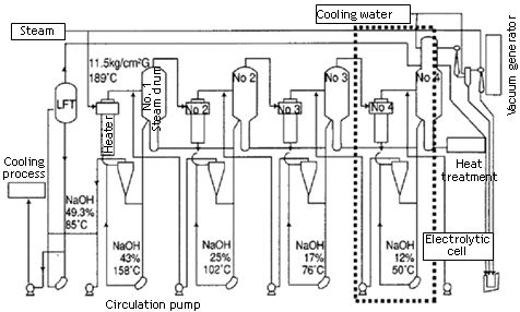
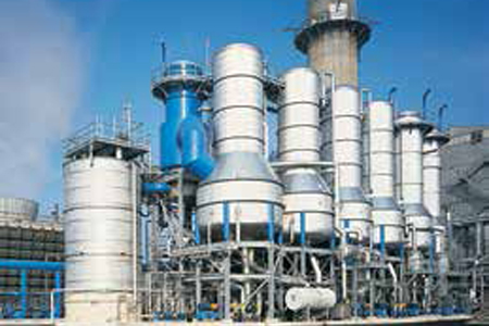
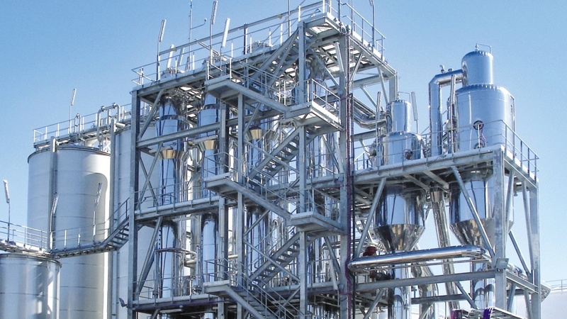
| Caustic Evaporation Plant The purpose of the plant is to concentrate the 32% caustic coming out of the electrolyzers to 48% caustic lye. This concentration is achieved by three multi effect evaporators. These evaporators concentrate the 32% caustic to 36%, 41% and eventually 48% caustic lye. Multi effect evaporators are usually fed by 3 possible feed systems: 1.Forward feed system: where feed and the heating medium both enter the first evaporator, in other words, co-currently. 2.Back ward feed system: In this system the feed enters counter-currently withrespect to the heating medium. 3.Mixed feed system: In this feed system the feed enters from the first evaporator,and the fresh heating medium may be introduced any where between the evaporators. The caustic evaporation plant at TPL employs the backward feed system. The evaporators are shell and tube type. The caustic flows in the tube side and steam circulates on the shell side. Glass wool insulated steel lines are used for circulation of steam. The caustic is carried in stainless steel lines up to a concentration of 36%, after which glass wool insulated Titanium lines are used for it. Steam is used as the heating medium. 32% caustic from the electrolyzers is preheated to 90° C by the 48% caustic coming out of the CEP plant. Steam coming from 2 nd evaporator is fed into the 1 st one,and caustic is concentrated to 36%. It is sent to a vapor separator, which is connected to a steam ejector, which separates the vapors from the caustic which are cooled and sent for recovery. The vapors separated from the 3 rd evaporator are used to pre-heat the 36% caustic before it enters the 2 nd evaporator; it is heated up to 110° C. Out coming steam from the3 rd evaporator is circulated inside the 2 nd one and the caustic is concentrated to 41%, and the temperature to 120° C. The vapor is separated and the used up steam is re-used in the1 st evaporator. The steam and caustic from the 3 rd evaporator pre-heat the 41% caustic to 160° C for more efficient concentration. Fresh steam enters the evaporator and concentrates the caustic to 48% caustic lye. The out coming caustic is cooled down by using its heat to preheat the caustic feeds to the other evaporators. It is finally cooled by cooling water lines to 45° C caustic lye. This is either sold as a product or sent for further concentration in the fusion plant. Fusion Plant The purpose of this plant is to concentrate the 48% caustic from the CEP plant to 98%Caustic flakes. The plant consists of three different multi effect evaporators. The temperature of thecaustic goes as high as 420° C in this plant. Normal steel apparatus may get corroded in such a highly alkaline and hot environment. Hence all lines and inner lining of the equipments are made up of Nickel. The plant consists of: 1.Pre-Concentrator (PC) 2.Rising Film Evaporator (RFE) 3.Falling Film/Final Evaporator (FFE)48% caustic liquor is fed by pump to the PC from top, operating on the product side under a pressure of approximately 65 torr (87 mbar). During a single pass through the PC, the caustic is concentrated up to approximately 55.4-55% caustic. The PC is heated by the vapors coming out of FFE. Before entering PC, a 5% sugar solution is added to the caustic. Sugar acts as a corrosion inhibitor. This forms a layer of Nickel oxide on the lines. This layer prevents further oxidation of Ni. The quantity of sugar to be added will be adjusted to the plant capacity each time. The NaOH 55% pump conveys the dilute acid to the pre heater atabout 90° C the pre-the concentrated caustic liquor is passed through a double tube type heatexchanger heated by condensed steam off the RFE. The outlet NaOH temperature is about 140-145° C. when passing the steam heated RFE, caustic soda is concentrated under a pressure of approximately 200 torr (267 mbar) up to 76% NaOH. The 76% caustic leaving the RFE is dipped into barometric seal pot. The PC and the RFE work under vacuum, which in both cases is produced by the vacuum ejector pump. The vacuum of 65 torr is required for the PC is produced by the 3 step injection group. The vapors from the PC are condensed in the mixing condenser via a barometric dipping tube. The condensed vapors and he cooling water are carried in to the wastewater pit. For the RFE, a vacuum of 200 torr is produced by the 2 step injection group. The 76% NaOH pump carried the caustic soda to the molten salt heated FC, where it is evaporated under normal pressure up to a min of 98.5%Naoh. The distributing device is fixed to the lower part of the separator and by this device; the caustic soda can be switched to either placer or drum filling station. In order to exclude atmospheric oxygen from penetrating into the system and to avoid corrosion the distributing system is superposed with nitrogen. The filling tubes to the flaker and to the drum filling station have been provided with a molten salt heating and the tube for NaOH 55-76% with steam heating. The well cooled flakes are then filled into 50 kg bags by means of the bagging scale. The balance to the nominal capacity of 100 tpd (37-20, maximum 50 tpd) of caustic melt can be fed via existing distributing devices to the drum filling unit. Control High Pressure Steam and Condensate System. RFE is heated with high pressure steam concentration of the leaving NaOH solution is determined by it outlet temperature, therefore a thermometer is installed in the outlet tube. Above the temperature controller TIC, the temperature of 160° C is adjusted which corresponds to the concentration of NaOH to 76% at 200 torr. From there corresponding command variable is given to the steam pressure control valve TCV in the steam tube, thus increasing or diminishing the steam throughput. The steam leaves RFE at the lower end. A level transmitter LT built in keeps the condensate which is under pressure constantly on a certain level. Control valve LCV is arranged in the flow direction after following caustic pre heater and receives its command variable from level control LIC. This arrangement guarantees an effective heat transfer in rising film evaporator and exploitation of the condensate cooling in the caustic pre heater. | |
|   | | Admin
Admin

عدد المساهمات : 3762
تاريخ التسجيل : 15/09/2009
العمر : 57
الموقع : مصر
 |  موضوع: رد: دراسة جدوى فنية تصميمية انشاء مصنع انتاج الصودا الكاوية القشور 99% والسائلة 48% فى مصر موضوع: رد: دراسة جدوى فنية تصميمية انشاء مصنع انتاج الصودا الكاوية القشور 99% والسائلة 48% فى مصر  الثلاثاء نوفمبر 20, 2018 1:12 pm الثلاثاء نوفمبر 20, 2018 1:12 pm | |
| | |
|   | | Admin
Admin

عدد المساهمات : 3762
تاريخ التسجيل : 15/09/2009
العمر : 57
الموقع : مصر
 |  موضوع: رد: دراسة جدوى فنية تصميمية انشاء مصنع انتاج الصودا الكاوية القشور 99% والسائلة 48% فى مصر موضوع: رد: دراسة جدوى فنية تصميمية انشاء مصنع انتاج الصودا الكاوية القشور 99% والسائلة 48% فى مصر  الثلاثاء نوفمبر 20, 2018 1:32 pm الثلاثاء نوفمبر 20, 2018 1:32 pm | |
| Ion membrane caustic soda plant Production capacity(NaOH 100%): Caustic Soda: 32%~50% solution, 98% flakes Hcl acid: 31%~33% NaClO: Active Chlorine, 12-14% Chlorine gas: In Liquid | |
|   | | Admin
Admin

عدد المساهمات : 3762
تاريخ التسجيل : 15/09/2009
العمر : 57
الموقع : مصر
 |  موضوع: رد: دراسة جدوى فنية تصميمية انشاء مصنع انتاج الصودا الكاوية القشور 99% والسائلة 48% فى مصر موضوع: رد: دراسة جدوى فنية تصميمية انشاء مصنع انتاج الصودا الكاوية القشور 99% والسائلة 48% فى مصر  الأحد نوفمبر 25, 2018 12:35 pm الأحد نوفمبر 25, 2018 12:35 pm | |
| | |
|   | | Admin
Admin

عدد المساهمات : 3762
تاريخ التسجيل : 15/09/2009
العمر : 57
الموقع : مصر
 |  موضوع: رد: دراسة جدوى فنية تصميمية انشاء مصنع انتاج الصودا الكاوية القشور 99% والسائلة 48% فى مصر موضوع: رد: دراسة جدوى فنية تصميمية انشاء مصنع انتاج الصودا الكاوية القشور 99% والسائلة 48% فى مصر  الأحد نوفمبر 25, 2018 12:36 pm الأحد نوفمبر 25, 2018 12:36 pm | |
| | |
|   | | Admin
Admin

عدد المساهمات : 3762
تاريخ التسجيل : 15/09/2009
العمر : 57
الموقع : مصر
 |  موضوع: رد: دراسة جدوى فنية تصميمية انشاء مصنع انتاج الصودا الكاوية القشور 99% والسائلة 48% فى مصر موضوع: رد: دراسة جدوى فنية تصميمية انشاء مصنع انتاج الصودا الكاوية القشور 99% والسائلة 48% فى مصر  الأحد نوفمبر 25, 2018 12:37 pm الأحد نوفمبر 25, 2018 12:37 pm | |
| | |
|   | | Admin
Admin

عدد المساهمات : 3762
تاريخ التسجيل : 15/09/2009
العمر : 57
الموقع : مصر
 |  موضوع: رد: دراسة جدوى فنية تصميمية انشاء مصنع انتاج الصودا الكاوية القشور 99% والسائلة 48% فى مصر موضوع: رد: دراسة جدوى فنية تصميمية انشاء مصنع انتاج الصودا الكاوية القشور 99% والسائلة 48% فى مصر  الأحد نوفمبر 25, 2018 12:56 pm الأحد نوفمبر 25, 2018 12:56 pm | |
| | |
|   | | Admin
Admin

عدد المساهمات : 3762
تاريخ التسجيل : 15/09/2009
العمر : 57
الموقع : مصر
 |  موضوع: رد: دراسة جدوى فنية تصميمية انشاء مصنع انتاج الصودا الكاوية القشور 99% والسائلة 48% فى مصر موضوع: رد: دراسة جدوى فنية تصميمية انشاء مصنع انتاج الصودا الكاوية القشور 99% والسائلة 48% فى مصر  الأحد نوفمبر 25, 2018 12:57 pm الأحد نوفمبر 25, 2018 12:57 pm | |
| | |
|   | | Admin
Admin

عدد المساهمات : 3762
تاريخ التسجيل : 15/09/2009
العمر : 57
الموقع : مصر
 |  موضوع: رد: دراسة جدوى فنية تصميمية انشاء مصنع انتاج الصودا الكاوية القشور 99% والسائلة 48% فى مصر موضوع: رد: دراسة جدوى فنية تصميمية انشاء مصنع انتاج الصودا الكاوية القشور 99% والسائلة 48% فى مصر  الأحد نوفمبر 25, 2018 12:58 pm الأحد نوفمبر 25, 2018 12:58 pm | |
| | |
|   | | Admin
Admin

عدد المساهمات : 3762
تاريخ التسجيل : 15/09/2009
العمر : 57
الموقع : مصر
 |  موضوع: رد: دراسة جدوى فنية تصميمية انشاء مصنع انتاج الصودا الكاوية القشور 99% والسائلة 48% فى مصر موضوع: رد: دراسة جدوى فنية تصميمية انشاء مصنع انتاج الصودا الكاوية القشور 99% والسائلة 48% فى مصر  الأحد نوفمبر 25, 2018 1:12 pm الأحد نوفمبر 25, 2018 1:12 pm | |
| Product specifications
Caustic soda at outlet of electrolyze
Noah 43%
Conc.= 50ppm
Nacl content temp.=88 c
Chlorine gas at outlet of electrolyze
Purity= 99,5 vol.%(dry base)
O2 content=0,5%vol. (dry base)
Temp.=85c
Water content= saturated
Hydrogen gas at outlet of electrolyze
Purity=99,9vol.(dry base)
O2content=0,03%vol.(dry base
Temp.= 88c
Water content= saturated
Hydrochloride acid = 30-33% by weight
Iron = 0,1 mgpl | |
|   | | Admin
Admin

عدد المساهمات : 3762
تاريخ التسجيل : 15/09/2009
العمر : 57
الموقع : مصر
 |  موضوع: رد: دراسة جدوى فنية تصميمية انشاء مصنع انتاج الصودا الكاوية القشور 99% والسائلة 48% فى مصر موضوع: رد: دراسة جدوى فنية تصميمية انشاء مصنع انتاج الصودا الكاوية القشور 99% والسائلة 48% فى مصر  الأحد نوفمبر 25, 2018 1:14 pm الأحد نوفمبر 25, 2018 1:14 pm | |
| Suggesting Production line
-Salt washery
-Primary brine purification
-Secondary brine purification
-Chloro alkai cell membrane electrolysis house
-Brine dechlorination
-Catholyte handling
-Chlorine gas handling
-Chlorine drying. Compression. Liquification. Storage
-Waste air dechlorination
-Hydrogen handling
-Utilities
-Effluent treatment
-HCL synthesis | |
|   | | Admin
Admin

عدد المساهمات : 3762
تاريخ التسجيل : 15/09/2009
العمر : 57
الموقع : مصر
 |  موضوع: رد: دراسة جدوى فنية تصميمية انشاء مصنع انتاج الصودا الكاوية القشور 99% والسائلة 48% فى مصر موضوع: رد: دراسة جدوى فنية تصميمية انشاء مصنع انتاج الصودا الكاوية القشور 99% والسائلة 48% فى مصر  الأربعاء نوفمبر 28, 2018 9:30 am الأربعاء نوفمبر 28, 2018 9:30 am | |
| | |
|   | | Admin
Admin

عدد المساهمات : 3762
تاريخ التسجيل : 15/09/2009
العمر : 57
الموقع : مصر
 |  موضوع: رد: دراسة جدوى فنية تصميمية انشاء مصنع انتاج الصودا الكاوية القشور 99% والسائلة 48% فى مصر موضوع: رد: دراسة جدوى فنية تصميمية انشاء مصنع انتاج الصودا الكاوية القشور 99% والسائلة 48% فى مصر  الأربعاء نوفمبر 28, 2018 9:32 am الأربعاء نوفمبر 28, 2018 9:32 am | |
| | |
|   | | Admin
Admin

عدد المساهمات : 3762
تاريخ التسجيل : 15/09/2009
العمر : 57
الموقع : مصر
 |  موضوع: رد: دراسة جدوى فنية تصميمية انشاء مصنع انتاج الصودا الكاوية القشور 99% والسائلة 48% فى مصر موضوع: رد: دراسة جدوى فنية تصميمية انشاء مصنع انتاج الصودا الكاوية القشور 99% والسائلة 48% فى مصر  الأربعاء نوفمبر 28, 2018 9:50 am الأربعاء نوفمبر 28, 2018 9:50 am | |
| PROPOSAL ON [size=37]CASUTIC SODA PLANT[/size] (20,000 MT per Year(100% The plant is to produce caustic soda and chlorine gas by salt and water through electrolyzing in electrolyzer. the plant is composed of following parts: l Primary Salt Water l Secondary salt water l Electrolysis Process l Dechlorine process l Chlorine Gas Treatment l Wasted Chlorine Treatment l Liquid Chlorine l Tank l Instruments and DCS system l Rectification Transformer(20KV Inlet Voltage)、Dynamic Power Distribution RAW MATERIAL QUALITY AND CONSUMPTION INDEX . 32% Caustic Soda Consumption Quota (calculated as 1 ton of 100% NaOH). | No. | Name and Spec | Unit | Qty. | Remark | | 1 | Salt(NaCl 100%) | ton | 1.584 | | | 2 | Sodium Carbonate (Na2CO3≥98%) | ton | 0.0082 | | | 3 | High-pure Hydrochloric acid (100% HCl) | ton | 0.0465 | | | 4 | Sodium Sulfite
Na2SO3≥95% | ton | 0.0015 | | | | | | | | | 6 | demineral water (EC≤5us) | m3 | 2.5 | | | 7 | Ion Exchange Resin | L | ≤0.0091 | | | 8 | Sulphuric Acid(H2SO4≥98%) | ton | 0.018 | For dryingCL2 | | 9 | Caustic Soda
(NaOH 100%) | ton | 0.0081 | | | 10 | Steam 0.3MPa G | t | 0.5 | | | 11 | Circulating Water
△t=8℃ | m3 | 100 | Max:38℃ | | 12 | Water for production 25℃ | m3 | 2.5 | | | 13 | Dynamic Power 380V | kWh | 180 | | | 14 | DC
Direct Current Consumption | kWh | 2200 | | | 15 | Ion Membrane | m2 | 0.006 | | | 16 | Instrument Air 0.6MpaG | Nm3/h | 300 | | | 17 | Process Air
0.6MpaG | Nm3/h | 200 | discontinuous | | 18 | Nitrogen Gas 0.6MpaG | Nm3/h | 300 | discontinuous |
.Liquid Chlorine Consumption Quota (calculated as 100% liquid chlorine for each ton) | No. | Name and Spec. | Unit | Qty. | Remark | | 1 | Dynamic Power(Including freezing amount) 380V | kWh | 95 | | | 2 | Sulphuric Acid 98% | kg | 1.4 | | | 3 | Nitrogen Gas 0.6MpaG | Nm3 | 2 | | | 4 | Circulating Water (for freezing machine group )32℃ | m3 | 50 | △t=8℃ |
3. 12.5% chloros (calculated as 1 ton of 12.5% chloros) | No. | Name and Spec. | Unit | Qty. | Remark | | 1 | Industry water | m3 | 0.4 | | | 2 | Dynamic Power 380V | kWh | 15~20 | | | 3 | Chilly Water 7℃ | m3 | 20 | △t=5℃ |
| |
|   | | Admin
Admin

عدد المساهمات : 3762
تاريخ التسجيل : 15/09/2009
العمر : 57
الموقع : مصر
 |  موضوع: رد: دراسة جدوى فنية تصميمية انشاء مصنع انتاج الصودا الكاوية القشور 99% والسائلة 48% فى مصر موضوع: رد: دراسة جدوى فنية تصميمية انشاء مصنع انتاج الصودا الكاوية القشور 99% والسائلة 48% فى مصر  الأربعاء نوفمبر 28, 2018 9:56 am الأربعاء نوفمبر 28, 2018 9:56 am | |
| PROCESS DESCRIPTION 1)Primary Salt Water After mixing uniformly in the water distribution trough, the dilute salt water from declorion, reclaimed wasted salt water, cleaning water from the treatment of salt slurry(plate frame filter press) and other salt waters, are conveyed with pressure by feeding pump, after heated by steam up to 50°C in heat exchanger, enter into salt melting trough sale melting barrel to melt the solid salt, until get the crude salt water which could meet concentration requirement(~310g/L). The crude salt water from the salt melting trough flow into the reaction trough R010a/b,added the Na2CO3,NaOH,and BaCl2 separately (or set individually the SO4 removal system for BaSO4 recovery) and make refinery reaction to remove Ca,Mg,SO4 ion in the crude salt water. By flowing out of reaction trough, the big mechanical impurities of the salt water are removed in strainer filter, confluence in intermediate trough. Then transfer the crude salt water to ceramic membrane filtering system by primary filtering feeding pump. The crude salt water entering filtering system is pressurized again by primary filtering circulating pump,then enter into primary filter. The cleaning liquid after filtering is the filtering salt water(SS≤1ppm),and flow into the filtering salt water tank confluence. When the solid matter of condensed salt water could meet the requirements, according to a certain proportion, part of them flow into the mud pool. The rest condensed water is still pressurized by primary filtering pump to recycle and filter again. The condensed salt water with higher solid percentage flowing into salty mud pool pressurized to transfer to plate filter, where separate the salt water from the slurry, and the salt water and cleaning water after filtering flow into the filtering trough to confluence, then transfer with pressure to water distribution trough, melting the salt again. 2)Secondary salt water This process is to refine the primary salt water further to meet the ionic membrane requirements. For the annual capacity of caustic soda plant is 20KTPY,the filtering salt water with 305±5g/l NaCl at 50ºC,flow into the filtering salt water trough at 24m3/h,then is conveyed to salt water heater up to 60ºC,and then conveyed to ion exchange resin tower. By ion exchange, make the Ca, Mg and other multivalent ion content less than specified value. The secondary refinery salt water from the ion exchange resin tower enter into electrolysis process by salt water head tank. There are 3 sets of ion exchange resin tower, filled by chelating resin. 3 sets of ion exchange resin tower operate alternately, by 2 sets on the line, and the rest one make the chelating resin regeneration out of the line. The first ion exchange resin tower is used to remove the multivalent ion, and the second set is for protection. Ion exchange resin tower switch for running and operation automatically every 24 hours. Chelating resin regeneration need 31wt% HCL, 32wt%NaOH and pure water. During chelating resin regeneration, after mixing with pure water,31wt% HCL is conveyed to ion exchange resin tower by sequencing valve. The concentration of solution is controlled by flow measuring system.32 wt% NaOH is treated in the same way. Acid and alkali wasted liquid produced during the regeneration will be sent out of battery limits. | |
|   | | Admin
Admin

عدد المساهمات : 3762
تاريخ التسجيل : 15/09/2009
العمر : 57
الموقع : مصر
 |  موضوع: رد: دراسة جدوى فنية تصميمية انشاء مصنع انتاج الصودا الكاوية القشور 99% والسائلة 48% فى مصر موضوع: رد: دراسة جدوى فنية تصميمية انشاء مصنع انتاج الصودا الكاوية القشور 99% والسائلة 48% فى مصر  الأربعاء نوفمبر 28, 2018 10:00 am الأربعاء نوفمبر 28, 2018 10:00 am | |
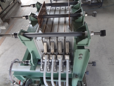
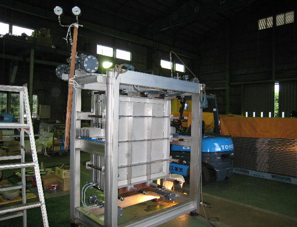
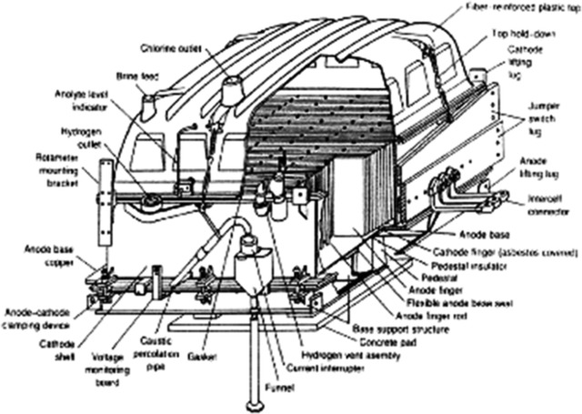
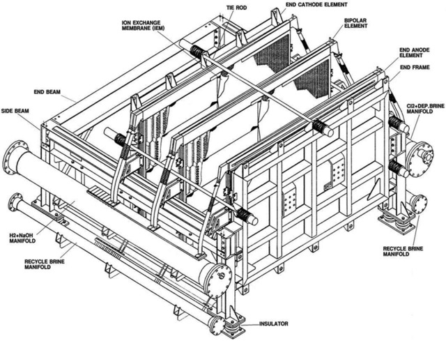
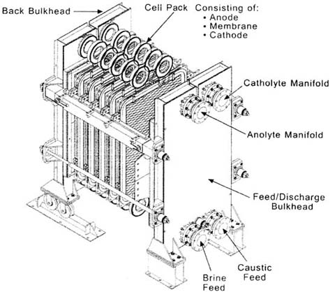
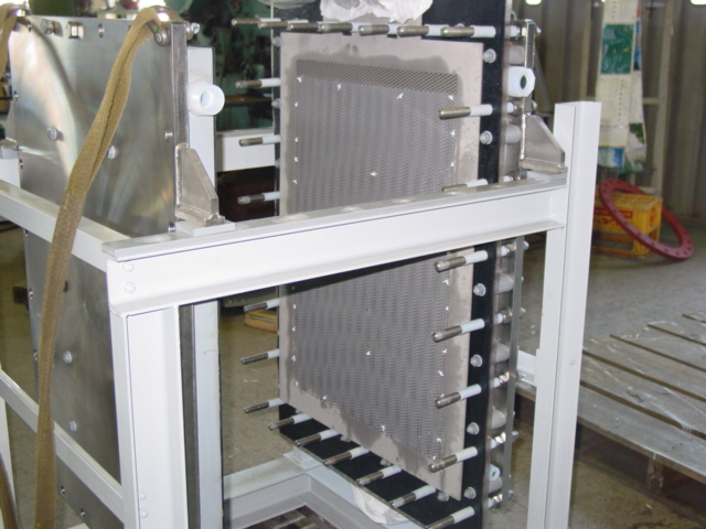
| Electrolysis Process Flowing into the anode chamber of electrolyzer, the secondary refined salt water makes the electrolysis to generate the chlorine gas. The reaction formula is as follows: NaCl— e —> Na+ + 1/2 Cl2 ↑ Dilute salt water with lower concentration after electrolysis. Due to the solubility of chlorine gas in the water, the dilute salt water contains free chorine, so the dilute salt water will be sent to be dechlorinated. In the cathode chamber, water is decomposed as H2.The reaction formula is as follows: H2O + e → OH- + 1/2 H2 ↑ OH- integrates with Na+ to generate 32% of alkali solution. 32% of alkali solution from the electrolysis flow into cathode liquid trough. Part of them mix with pure water and return to cathode chamber of electrolyzer, and the other part as the product will be sent out of the battery limits. H2 and CL2 generated from anode chamber and cathode chamber is conveyed to out of battery limits for chlorine and hydrogen process. Electrolysis process is made up of 2 sets of electrolyzer and concerned equipments, such as dilute salt water trough, dilute salt water pump, alkali tank, liquid alkali pump, cathode liquid cooler, and pipe filter etc. Each electrolyzer is made up of 60 pairs of unit troughs, 60 sheets of ion exchange membrane and its accessories. Electrolyzer unit is made up of metal anode, active cathode, anode chamber and cathode chamber. Accessory is made up of hydraulic system, feed inlet and outlet general pipe, flexible conduit of anode and cathode liquid inlet and outlet the gasket of anode and cathode, flexibleness cable connecting electrolyzer with fixed conducting copper, and protection device against electricity corrosion etc. Refined salt water from secondary salt water refinery process is conveyed to anode and cathode liquid inlet general pipe via salt water electrolysis trough. The flow is controlled by flow meter of each electrolyzer to keep the concentration of anode liquid up to the specified value. The flow value is made cascade control by direct current of each electrolyzer. Hydrochloric acid concentration 17% is used to neutralize OH ion passing through the ion membrane, then is continuously conveyed to anode chamber with anode liquid via flowmeter. Refined salt water electrolyze in the anode chamber to generate chlorine gas, and meanwhile decrease the NaCl concentration. NaCl decomposition rate between inlet and outlet of electrolysis trough is about 50%. There are two flexible hose, one for connecting inlet general pipe, and the other one for connecting outlet general pipe. After electrolysis, the mixture, chlorine gas and dilute salt water discharge into anode liquid general pipe through hose, and separate gas from liquid in the general pipe. Dilute salt water confluence in the salt water tank and then is sent to dechlorination . Chlorine is collected in the chlorine gas general pipe and then is sent to head trough of dilute salt water. Consequently, the water in chlorine is separated and drip. Then chlorine is sent to out of battery limits. The chlorine pressure is controlled by pressure controllers installed on the chloride general pipe. The purity of chloride gas is about 99vol% (dry basis). Part of dilute salt water with chlorine is returned to refinery salt water pipeline against titanium pipe corrosion. The structure of cathode liquid chamber is similar to anode liquid chamber. There are two inflexible hoses in each cathode liquid chamber, one for connecting feed inlet general pipe, and the other one for connecting feed outlet general pipe. The caustic soda after dilution is sent to general pipe inlet of each electrolysis trough through head tank of caustic soda, then sent to cathode liquid chamber through inflexible hose. Add the pure water at the general pipe inlet of cathode chamber to keep the caustic soda concentration in the cathode liquid at the specified value. The flow of pure water is controlled by flow meter. The set value of flow meter is controlled by direct current or cathode liquid concentration cascade. Cathode liquid cooler is installed between caustic soda pump and caustic soda head tank. Cathode liquid cooler together with temperature controller control the cathode liquid temperature. The cathode liquid adding into electrolyzer is monitored by temperature controller. After electrolysis, hydrogen and caustic soda is generated in the cathode chamber. The mixture of hydrogen and caustic soda discharge to general pipe of cathode liquid outlet, and is separated as gas and liquid in the general pipe. Cathode liquid confluence in the caustic soda trough, and is conveyed by caustic pump. Part of caustic soda as the product is conveyed to intermediate tank, and the rest returns to head tank of caustic soda. The finished product is conveyed to out of the battery limits. Caustic soda flow meter measure the flow and general amount of product. Minor cathode liquid is conveyed to density meter to measure the finish product concentration. Hydrogen confluence in the general pipeline of hydrogen, and is conveyed to head of caustic soda tank, where the moisture in hydrogen is separated and drip. Then hydrogen is conveyed to out of battery limits. The hydrogen pressure is controlled by pressure controllers installing on the hydrogen general pipe. Controllers is made cascade control by chloride gas pressure so as to keep the pressure between hydrogen and chloride at the specified value. The purity of hydrogen is 99.9vol% (dry basis). | |
|   | | Admin
Admin

عدد المساهمات : 3762
تاريخ التسجيل : 15/09/2009
العمر : 57
الموقع : مصر
 |  موضوع: رد: دراسة جدوى فنية تصميمية انشاء مصنع انتاج الصودا الكاوية القشور 99% والسائلة 48% فى مصر موضوع: رد: دراسة جدوى فنية تصميمية انشاء مصنع انتاج الصودا الكاوية القشور 99% والسائلة 48% فى مصر  الأربعاء نوفمبر 28, 2018 10:02 am الأربعاء نوفمبر 28, 2018 10:02 am | |
| Dechlorination process For the dilute salt water from electrolyzer, part of them is added into hydrochloric acid to adjust PH(1-2.5), entering into chlorate decomposition trough to decompose chlorine, then return to anode liquid tank. The other part is sent to top of dechlorination tower, and is separated at the negative pressure. The dilute salt water after dechlorination flow into dechlorination salt water trough with free chlorine 50mg/l, and added into caustic soda, then is added into Na2SO3 to remove free chlorine further after adjusting PH. The chemical reaction formula is as follows: Na2SO3 + CL2 +2 NaOH → Na2SO4 + 2NaCL + H2O Dilute salt water is sent to primary refinery process by dechlorination salt water pump. After dechlorination, the chloride gas is cooled by chlorine cooler and is separated water, then is sent to general pipe of chloride gas . | |
|   | | Admin
Admin

عدد المساهمات : 3762
تاريخ التسجيل : 15/09/2009
العمر : 57
الموقع : مصر
 |  موضوع: رد: دراسة جدوى فنية تصميمية انشاء مصنع انتاج الصودا الكاوية القشور 99% والسائلة 48% فى مصر موضوع: رد: دراسة جدوى فنية تصميمية انشاء مصنع انتاج الصودا الكاوية القشور 99% والسائلة 48% فى مصر  الأربعاء نوفمبر 28, 2018 10:05 am الأربعاء نوفمبر 28, 2018 10:05 am | |
| Chloride Gas Treatment High-temperature wet chloride gas(about 75-80ºC) from electrolyzer enter into the bottom of chlorine water cleaning tower, from top to bottom, contact the chloride water which enter from the top, to clean the salt mist and organic matter, and exchange heat. Until wet chlorine is cleaned and cooled at about 40±5ºC, flow out of top tower. Chloride water is recycled by chloride water pump, cooled by cooler to ensure circulating chloride water at ~30ºC when enter into the chlorine cleaning tower. Redundant chloride water is sent out of the battery limits to dechlorine tower . The wet chlorine from chlorine water cleaning tower enter the pipe at the upper cover of titanium tubular exchanger , cooled by 8ºC of cooling water in the shell to 12-15ºC, then flow out of bottom cover outlet into mist arresteor, after mist removal, enter into drying system. During the process, the condensing water flow out to chloride water tank through water seal. It also can adopt two-level titanium tubebank for cooling. Cooling by recirculating cooling water to ~30ºC for primary, and by cooling water at 6ºC to 12ºC-15ºC for secondary so as to save energy. Wet chlorine from mist collector enter into the bottom of major packed tower, and from bottom to top, passing the packed layer, and contact sulphuric acid completely to be dried, then chloride flow out the top tower into inlet of secondary packed and bubble-cap tower. The chloride gas from the top of primary packed tower enter into the bottom of secondary packed and bubble-cap tower, from the bottom to top, passing all tower plates in the tower, to be dried by contacting the sulfuric acid completely. Flowing out the top tower, the chlorine is removed acid mist through acid mist collector to become dry chloride gas with moisture content at 100 ppm(wt),then enter into the chloride gas compression system. The 98%wt of sulfuric acid at the bubble-cap segment of secondary packed and bubble-cap tower, from the 98%wt acid head tank, all pass the bubble-cap segment once. Feed 98%wt sulfuric acid by meter pump from sulfuric acid tank. Sulfuric acid out of bubble-cap segment is used for packed segment, cooled and recycled by circulating acid pump and circulating acid cooler(8±3°C cooling water) (Inlet for circulating acid at reciprocal first or second bubble-cap tower plate). Control the inlet temperature at ~20°C.When the concentration is reduced to 88%wt or liquid level of tower bottom at a certain value, pump it into sulfuric acid inlet of primary packed tower. About 88%wt of Sulfuric acid from the packed segment of secondary packed and bubble-cap tower, enter into the upper segment of primary packed tower, cooled and recycled by diluted sulfuric acid circulating pump and diluted sulfuric acid cooler. Control the inlet temperature at ~20°C. When its concentration is reduced at about 75%wt or the liquid level of tower bottom at a certain value, pump it into diluted sulfuric acid tank, then packaging for selling. | |
|   | | Admin
Admin

عدد المساهمات : 3762
تاريخ التسجيل : 15/09/2009
العمر : 57
الموقع : مصر
 |  موضوع: رد: دراسة جدوى فنية تصميمية انشاء مصنع انتاج الصودا الكاوية القشور 99% والسائلة 48% فى مصر موضوع: رد: دراسة جدوى فنية تصميمية انشاء مصنع انتاج الصودا الكاوية القشور 99% والسائلة 48% فى مصر  الأربعاء نوفمبر 28, 2018 10:08 am الأربعاء نوفمبر 28, 2018 10:08 am | |
| Wasted Chlorine Treatment Wasted chlorine which need to be absorbed, enter into the wasted chlorine treatment tower (adopt packed tower or spraying tower),contact the liquid alkali from the top completely. Chloride gas reacts with caustic soda to generate sodium hypochlorite. Residue tail gas is exhausted to air from the top of tower by air fan (require that chlorine content ≤ 1mg/M3). Absorbing alkali liquid flow to alkali circulating tank from the tower bottom, then is sent to alkali cooler by alkali circulating pump, after removing the reaction heat, return to the tower top and make the next turn of absorption. Until the absorbing alkali can meet the hypochloric acid quality requirements(effective chloride ≥10%wt, chloride content ≤1%wt).Pump to package department for selling. Newly prepared liquid alkali(16~20%wt) is supplemented to liquid alkali circulating tank(use two sets alternately then sent into the top tower by liquid alkali circulating pump Newly prepared liquid alkali (16~20%wt) is also sent to head tank of liquid alkali. When there is power failure suddenly in the whole factory or circulating pump fail to offer the liquid alkali, the cut-off valve on outlet pipeline is open automatically(set concerned interlocking return circuit in the DCS system Liquid alkali flow into wasted chlorine treatment tower by level difference, absorb chlorine in chlorine system(chlorine flow into tower by pressure difference). Liquid alkali amount in head tank of Liquid alkali need meet the chloride gas requirements in the chloride gas system. | |
|   | | Admin
Admin

عدد المساهمات : 3762
تاريخ التسجيل : 15/09/2009
العمر : 57
الموقع : مصر
 |  موضوع: رد: دراسة جدوى فنية تصميمية انشاء مصنع انتاج الصودا الكاوية القشور 99% والسائلة 48% فى مصر موضوع: رد: دراسة جدوى فنية تصميمية انشاء مصنع انتاج الصودا الكاوية القشور 99% والسائلة 48% فى مصر  الأربعاء نوفمبر 28, 2018 10:11 am الأربعاء نوفمبر 28, 2018 10:11 am | |
| Liquid Chlorine After the chlorine treatment process, the dried chlorine is sent to liquefier of chlorine by chlorine pump, Freon gas is condensed to liquid by freezing machine group, after throttling, then sent to liquefier of chlorine gas and exchanges heat with chlorine gas directly. Liquefy the chlorine gas below -25℃, then sent to finished product tank after liquid-gas separation. Get bleaching liquor in tail gas, and the freon gas returns to freezing machine group to recycle. H2 Gas Treatment Hydrogen which comes out by the electrolyzer, its temperature is lower than electrolyzer's temperature slightly, and includes the saturated air, simultaneously includes the alkali entrainment. Therefore should carry on cooling and the wash in the production process, the cooling hydrogen enters the compressor to compress the evacuation postorder construction 50% Caustic Soda Evaporation Product is passing the evaporator in counter current sequence. Prior to feed to Effect 1, the product is preheated in two heat exchangers, in parallel on the product side. Preheater1 is utilizing the heat in the steam condensate from Effect 1, while preheater 2 is recovering the heat in the final product. The final product is further cooled to 45 °C in product interchanger using cooling water. The vacuum is maintained by a vacuum pump, connected to the condensate outlet of the condenser, removing the non condensable gasses. | |
|   | | Admin
Admin

عدد المساهمات : 3762
تاريخ التسجيل : 15/09/2009
العمر : 57
الموقع : مصر
 |  موضوع: رد: دراسة جدوى فنية تصميمية انشاء مصنع انتاج الصودا الكاوية القشور 99% والسائلة 48% فى مصر موضوع: رد: دراسة جدوى فنية تصميمية انشاء مصنع انتاج الصودا الكاوية القشور 99% والسائلة 48% فى مصر  الأربعاء نوفمبر 28, 2018 10:12 am الأربعاء نوفمبر 28, 2018 10:12 am | |
| WORKSHOP AREA Production workshop of 20000T /Y Caustic Soda | No. | Building Name | Floor area ㎡ | Building area ㎡ | Construction type | Building height m
| Floor Number | | 1 | Salt storehouse | 18×50=900 | 900 | Steel-concrete | 10 | 1 | | 2 | Primary Salt Water workshop | 10×30=300 | 10×30×3=900 | Concrete | 8 | 3 |
3 | Caustic soda workshop | 60×30=1800 | 50×18×2=1800(Electroanalysis plant) | Steel-concrete | 12 | 2 | | 10×20×4=800( Commutation plant/Declorine) | 21 | 4 | | 4 | CL2 & H2&Naclo | 50×20=1200 | 50×15×3=2250 | Steel-concrete | 18 | 3 | | 5 | Liquid chlorine& Packing | 50×20=1000 | 50×20=1000 | Steel-concrete | 10 | 1 | | 6 | HCL | 20×20=400 | 7×12×5=420 | Steel structure | 12 | 2 | | | Total | 5600 | 8070 | | | |
| |
|   | | | | دراسة جدوى فنية تصميمية انشاء مصنع انتاج الصودا الكاوية القشور 99% والسائلة 48% فى مصر |  |
|
| | صلاحيات هذا المنتدى: | لاتستطيع الرد على المواضيع في هذا المنتدى
| |
| |
| |










![[MSF+3.jpg]](https://2img.net/h/4.bp.blogspot.com/_SynCnHGx75g/Shl2T3oVhsI/AAAAAAAAAEY/_7oem5pvQ3I/s1600/MSF%2B3.jpg)

