Admin
Admin

عدد المساهمات : 3762
تاريخ التسجيل : 15/09/2009
العمر : 57
الموقع : مصر
 | موضوع: كيف نصمم فلاتر رملية لترشيح المياه  السبت يناير 15, 2011 3:28 am السبت يناير 15, 2011 3:28 am | |
| Types of Filters
by
colonel.dr
bahaa badr
chemical consultant
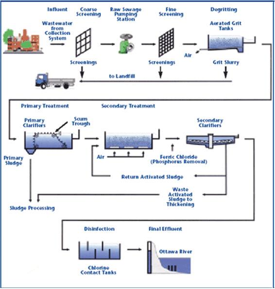
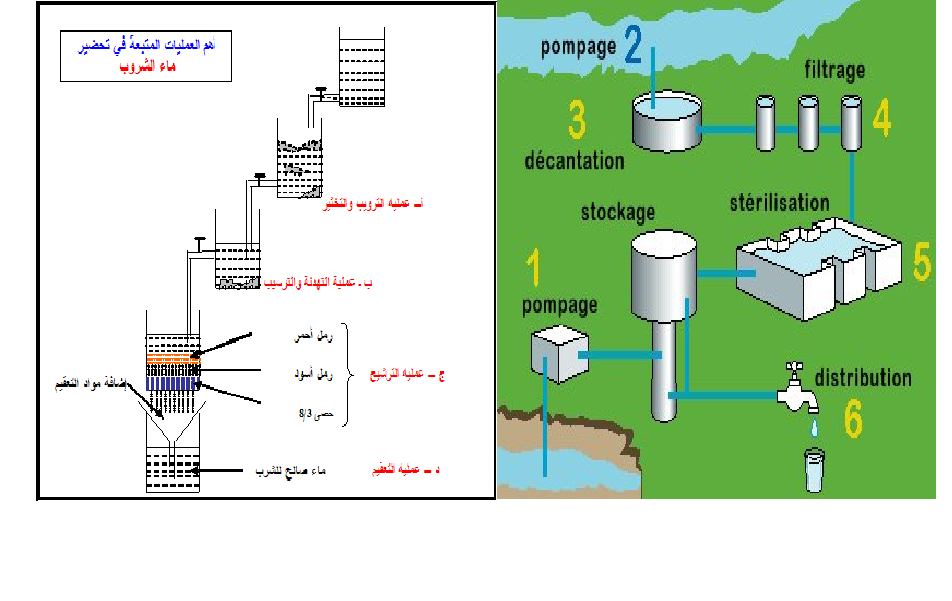
Screening will remove the larger suspended solids form water, and sedimentation following chemical coagulation will remove most of the residual suspended matter. However, there will usually remain some fine floc particles and other suspended matter. To remove them, to reduce still further the bacterial content of the water, and to ensure the production of a clear and attractive water, filters are used.
Essentially a filter consists of a bed of granular material to remove suspended solid form the water, with devices to maintain a uniform rate of flow through the bed and with provisions for reversing the direction of flow of water periodically to wash accumulated solids from the filter medium.
In municipal water-treatment practice, sand filters are employed almost exclusively, though some plants utilize finely crushed anthracite coal instead of sand for the filter medium.
There are two general types of sand filters in use for water purification. They are classified as slow sand filters and rapid sand filters. They differ primarily in the rate at which they operate, but there are also essential differences in theory and in operation. The rapid sand filters are further classified as gravity filters and pressure filters.
In rapid sand filtration, the water is passed downward through the sand at a relatively high velocity, usually at a rate of 2 to 3 gpm per square foot of filter area, and the rate is carefully controlled. After passing through the sand bed and a supporting layer of gravel, the water is collected by an underdrainage system and discharged into a clear well from which it is drawn for consumption.
Pretreatment by coagulation and sedimentation is essential in order to remove as much as possible of the suspended matter, thus lessening the load on the sand bed. Because of the high rate, the sand bed tends to clog rather quickly and must be washed frequently. This accomplished by reversing the flow of the water through the gravel layer and the sand bed. Clear water for washing is stored in and elevated tank or supplied by a special pump.
The main elements of a gravity-type rapid sand filter are shown in the figure below; The water from the sedimentation basin enters the pipe gallery through a main and its distributed to the filters units through valved pipelines. The water in each filter unit is maintained at a depth of 4 to 5 feet over the sand by means of controls, the total depth from water surface to underdrains being 8 to 10 feet.
The rate of passage of the water through the sand is controlled to ensure a uniform rate of filtration. When the sand becomes dirty, as indicated by an excessive loss of head for the water passing through it, the feed to the filter is cut off, the bed is drained down, and wash water is forced upward through the gravel and sand.
The dirty water resulting from washing overflows into wash-water troughs and is discharged through drains into a sewer for disposal.
After the sand is washed, the filter is again placed in operation, but the water first filtered is wasted because wash water must be removed from the interstices of the filter and a surface mat must be allowed to form again on the sand. This mat is composed mainly of floc particles, not all of which settle in the sedimentation basin. It is effective in removing very fine particles as well as bacteria during the filtration process.
Filters are usually rectangular in shape and are built of concrete but in smaller plants circular units, built either of steel or of concrete, are used.
Pressure filters have the same general characteristics as rapid sand of the gravity type filters and operate in the same way. The filter media and the underdrains are contained in a steel tank, and the water is pumped through the filter. Preliminary treatment is essential if the water is turbid or contain appreciable amounts of suspended matter. A variation of the pressure filter employing sand is the diatomite filter, which utilizes diatomaceous earth as a filtering medium.
In a slow sand filter the water is passed through the sand layer at a low velocity, normally at the rate of 0.05 to 0.15 gpm per square foot. Pretreatment is often advantageous but is not essential unless the water is turbid; slow sand filters will not satisfactorily handle waters with turbidities above 5 mg/l. Cleaning is required only at long interval of time if the water is relatively clear. It is accomplished by removing a thin surface layer of the sand.
RATES OF OPERATION
The standard rate of operation of rapid sand filter is 125 mgd per acre of filter area or 2 gpm per square foot. Within the past few years there has been a decided trend toward increasing this rate. Filters in a number of plants are being operated at 3 gpm and a few at 4 gpm, per square foot. In many recently designed filters piping and controls have been installed to permit future operation at the 4 gpm rate, even though the initial rate will be 2 gpm.
Pressure filters operate within the same rate ranges as do gravity-type rapid sand filters when used for community water treatment. Because pretreatment may be less effective for pressure filters than for standard-type filters, rates should be kept comparatively low. Difficulty in pretreatment arises from the fact that plants with pressure filter are usually small and lack skilled operation, and also because facilities for adequate coagulation and settling are not always provided.
Operating rates for slow sand filters may range from 3 to 9 mgd per acre, but usually are between 5 and 6 mgd. The character of the applied water, especially its suspended-matter content, is usually the governing factor.
When the filter medium is diatomaceous earth, the container is a steel tank and support for the layer of earth is provided by a porous septum of tube. In starting a filter cycle, the diatomaceous earth is added to the incoming water until a layer of the desired thickness is deposited over the septum. The feed of earth is then discontinued, and filtering starts.
When the filter needs cleaning, the flow of water is reversed and the sued coating of diatomaceous earth is wasted. Another coat is then applied, and filtration is again started. Operation may be at rates as high as 15 gpm per square foot of surface, but normally it is between 2 and 3 gpm.
The length of run depends on the suspended matter content of the applied water. In some cased the feeding of diatomaceous earth is continued at a lower rate during the filtering process. Under some conditions longer runs between washings are obtained with a lesser amount of filter medium by this means.
THE SAND BED
In a rapid sand filter the depth of the sand bed is usually at least 24 inches and may be more. In a slow sand filter, the depth is generally about 36 inches, but occasionally is as little as 24 inches. Sand for filers must be free from clay, loam, organic matter, and lime particles.
Also the sand particles must be fairly uniform and of proper size. Fine sand tends to clog quickly and requires frequent washing. Very coarse sand permit the passage of some suspended solids and perhaps also more bacteria. Crushed anthracite coal, when used, conforms generally to applicable specifications for sand. Filter sand is classified in regard to its size and uniformity by means of two properties called the effective size and the uniformity coefficient. The requirements in regard to these properties apply also to anthracite media.
EFFECTIVE SIZE OF SAND
As a basis for comparing different sands, the effective size is taken as the size of the grain that is larger than 10 percent by weight of all the particles comprising the sand.
It is assumed that sand composed entirely of grains of this effective size would offer the same frictional resistance to the flow of water as will the actual sand. The effective size is determined by passing standard sieves arranged in order, the one having the largest mesh being used first. The material retained on each sieve is weighed separately, and the total weight larger than each size is also determined. These total weights area expressed as percentages of the weight of the entire sample.
The required effective size is determined by inspection of the results or by first plotting a graph with the sizes of sieves as abscissas and the percentages as ordinates and then determining the abscissa that corresponds to an ordinate representing 10 percent.
Sand for rapid sand filters should have an effective size of 0.35 to 0.55 mm; for slow sand filters the effective size is usually 0.20 to 0.4 mm. In rapid sand filters, there is a tendency to sue coarser sand and to utilize chlorination for final removal of the bacteria. Coarser sands permit longer filter runs and can be washed more efficiently.
UNIFORMITY OF SAND
The effective size of the sand merely indicates the minimum size of 90 percent by weight of the sand. It gives no information about the degree of variation in the sizes of the particles or about the sizes of the largest and smallest grains.
Considerable variation in individual grain size will affect the efficiency of the filter and therefore undesirable. The degree of variation is expressed by the uniformity coefficient. This value is obtained by finding the size of that particle which is coarser than 60 percent by weight of the sand and then dividing that size by the effective size of the sand.
Thus, if a sand has an effective size of 0.4 mm. and 60 percent of the sand passed a 0.59 mm. screen, the uniformity coefficient is:
0.59 / 0.40 = 1.5
For rapid sand filters a uniformity coefficient of 1.5 to 2.0 is preferred; for slow sand filters 1.6 to 2.5 or 3.0 is satisfactory.
THE GRAVEL LAYER
The gravel layer in a filter has practically no part in the purification of water. Its principal function is to support the sand layer and, in a rapid sand filter, to distribute the wash water. The gravel layer is usually 12 to 24 inches deep in a rapid sand filter, and perhaps is slightly less in a slow sand filter.
The particles should be well graded and place in courses of about 3 inches thick. The coarsest particles, which are 2 to 3 inches in size should be at the bottom. The top layer, which is directly beneath the sand, may be 0.10 inches in size. Distribution of the wash water is the critical function of the gravel layer, and careful grading of material and equally careful placement are important.
ARRANGEMENT OF UNITS
The primary function of a water-treatment plant is to produce a safe, palatable, and attractive water and everything in design should consider this function. The general features of design that should be followed are based on experience. In some plants the layout consist of a pipe gallery with filters on one side and mixing basins and sedimentation basins on the other side.
In many installations the filter units are located on both sides of the pipe gallery. Local conditions, including topography, size of plant, and climate are influencing factors. An operating floor in a building forms the roof of the pipe gallery and is elevated slightly above the tops of the filters.
Pumps are usually grouped at one end of the building. Controls must be located on the operating floor. Provision must be made for chemical storage and for feeding equipment. A tank for wash water should be located nearby, or pumps of sufficient capacity must be provided.
An office and a laboratory are essential. A clear well should be provided to store the filter water. It should be large enough to supply the needs of the community for from 3 to 24 hours. Its capacity depends on whether the filters are to be operated 6, 16, or 24 hours per day and on how much distribution storage is to be provided. The clear well may be under the filters or elsewhere if another location is more convenient. Provision should be made in the design for additional filters and sedimentation basins at some future time.
Filters and sedimentation basins are sometimes covered with a roof, but often are open. In a cold location, a cover will usually be desirable to prevent ice formations and in a warm location algae growth should be prevented by a cover.
DESIGN OF FILTER UNITS
The size of a filter unit is determined by the required capacity of the plant, the number of units judge necessary for flexible operation, and the number of hours per day that the plant will operated. The latter factor is and economic one that balances the cost of storage against the extra expense of building a larger plant and of operation for 16 to 24 hours instead of 8 hours.
Frequently, the capacity of the clear well, which is the plant storage, does not exceed one-third to one-half the daily capacity of the plant. Therefore, distribution storage is needed to provide water for periods when the plant does not operate. Large plants are normally operated 24 hours per day; small plants, 8 to 12 hours. In larger plants, each filter unit has a capacity of 1 to 3 mgd; dimensions of a 1-mgd unit are normally 18 by 20 ft. Units in small plants vary in size from 9 to 10 ft to 10 to 18 ft. A 9 by 10 ft unit will filter 250,000 gallons in 24 hours or about 83,000 gallons in 8 hours.
An equation, which may be used as a guide for the number of filter units, has been developed by Morrell and Wallace.
N = 2.7 ( Q )½
where N = number of filter units
Q = plant capacity, in million gallons per day.
There should be at least two filter units in any plant. In a plant whose capacity is greater than 2 mgd, no simple unit should have a capacity exceeding one-fourth of that of the plant.
Extremely large filter units may create problems in the design of the underdrainage system, because uniform distribution of wash water may then be difficult.
In designing a filter, consideration should be given to several factors.
To prevent possible contamination of filtered water by raw water, there should be no place in the plant where raw water and finished water area separated only by only a single wall.
In the influent pipe or channel carrying flocculated water, the velocity should be more than 1 to 2 fps, to prevent eddies and currents and possible comminution of the floc.
If the wash-water discharged from the filter flows to a sewer, an air gap should be provide to prevent contamination of the water in case the sewer should back up because of clogging or storm-flow condition with flooding.
DEPTH OF FILTER
The depth of a filter is the sum of the following:
The height of the underdrainage system;
The total depth of the layer of gravel and sand;
The depth of water over the sand; and
The freeboard, or clear distance above the water level.
With a freeboard of 1 ft, a water depth of 5 ft, a combined sand and gravel depth of 3.5 ft, and an allowance of 1 ft for underdrains, the filter shell will be 10.5 ft. deep.
UNDERDRAINAGE SYSTEMS
The system of underdrains in a filter unit must collect the filtered water. It must also be capable of passing the wash water at a rate of 15 gpm per square foot or more, depending on the design, while applying it evenly over the under portion of the gravel or sand bed.
Various types of construction are used for underdrainage systems:
A grid of pipes into which strainers are tapped;
Vitrified clay blocks with perforations at intervals;
Porous silica plates mounted on supports, a gravel layer not being required; and
Openings in the floor shaped like inverted truncated pyramids and space 12 inches apart filled with concrete or earthenware balls of various sizes, the largest at the bottom.
Because the rate of application of the wash water is so much higher than the rate of filtering, underdrain design is governed primarily by the necessity for even distribution of wash water. Such even distribution may be obtained by keeping head losses in the orifices high or by using a double bottom of porous plates or clay blocks.
For satisfactory distribution of the wash water when using the pipe-grid system, the pressure at the strainers or orifices should be about 15 psi and the velocity of flow should be not greater than 8 to 10 fps.
Laterals must be spaced 6 to 12 inches on centers but maximum length of a lateral should not exceed 60 times the diameter in order to have uniform pressure and distribution throughout the length.
The total area of orifices in the strainers or laterals should be 0.2 to 0.3 percent of the surface area of the filter. The orifices in perforated pipe underdrains are usually 0.25 to 0.5 inches in diameter, and spacings may vary from 3 inches for 0.25 in. openings to 8 inches for 0.5 in. openings.
The cross-sectional area of the laterals should range from twice the total orifice area for 0.25 in. orifices to 4 times the orifice area for 0.5 in. orifices.
The header feeding the underdrainage system should provide the required amount of wash water at a velocity of 6 to 8 fpc. A basis for design is to provide a cross-sectional area in the header 1.5 times the total area of openings in the strainers or in the orifices.
CLEAR-WELL CAPACITY
The desirable capacity of the clear well of a filter depends on factors both within and without the plant. The principal factors within the plant are the number of filter units and the number of hours that the plant is operated daily.
With 24-hr operation of a plant that contains several filter units, less clear-well capacity is required. Normal repairs and maintenance will not materially affect production. However, the provision of storage capacity in the distribution system is the principal factor affecting clear-well size.
If this distribution storage is ample to care for peak loads, fires, brief plant shutdowns, and other such conditions, less clear-well capacity is indicated. Where there is amle distribution storage, the clear well should have sufficient capacity to meet the normal demand for at least 3 to 6 hours. Consideration should be given to the relative costs of providing storage in the clear well and in the distribution system.
LOSS OF HEAD
As water is passed through a filter, suspended material is deposited on top of the bed and in the upper layers of the sand. This material increases the resistance to the flow of water through the sand.
When a filter unit is first put into service, the loss of head is comparatively small, whereas, after an operating period of 20 to 30 hours it may be quite large. When the losss becomes too great, the filter is washed. In operation, loss of head is indicated by gages which measure the difference between the surface of the water over the filter and the piezometric pressure on the filter outlet.
When a filter is operated under a suction, the piezometric level of the water leaving the filter is lower than that of the bottom of the sand layer, and it is said that the head is negative. Although this condition permits operation of the filter with a relatively high loss of head, it also tends to release gases dissolved in the eater and may cause air binding in the filter. Operation under negative head is considered undesirable.
The loss of head caused by the passage of the water through the sand can be computed approximately, but water temperatures, sand characteristics, and many other factors introduce uncertainties in the results. In a clean filter, the initial loss of head ranges from 1.5 to 2.5 feet under normal operating conditions.
The loss of head increases as the filter is continued in operation. It is desirable to be able to operate a filter with head losses up to 8.5 feet. To do so, careful design will usually be needed. To the loss of head through the filter itself must be added that in the underdrainage system and the flumes or pipe carrying the water to the clear well.
The water level in the clear well, when filled, should be 12 to 13 feet below the surface of the water over the filters. Provision of this amount of head, which is especially necessary when higher rates of filtration are sued, introduces problems in design. If and allowance of 3 feet is made for losses through the mixing and settling units and 13 feet for losses through the filter and the following piping, the clear-well, when full, will be 16 feet below the intake level.
A clear-well depth of 14 feet then requires an over-all head through the plant of 30 feet, and it is often difficult to obtain this head without excessive cost.
WASHING THE FILTER
A filter unit is washed when the filtering medium has become so dirty that the maximum gravity head is required to force the water through the bed. Also, in plants operated only part of the day, the filters are sometimes washed at the end of each operating period.
However, this practice is wasteful of wash water, which is filtered water. For instance, washing when dictated by loss of head requirements may use perhaps 4 percent of the water that is filtered, whereas washing at the end of each 8 hour operating period requires 10 to 12 percent of the water filtered.
The purpose of washing is to remove from the filter bed all suspended matter that has collected on and in the sand. Washing is accomplished by reversing the flow of water through the filter, but using a much higher rate. In most plants an upward rate of flow of 24 inches per minute is used; in a few plants, higher rates are employed occasionally up to 60 inches per minute.
A 24-in rate is attained by applying the wash water at the rate of 15 gpm per square foot filter area. The filtered water used for washing may be supplied from an elevated tank or by a pump drawing from the clear well or other source. At least 150 gallons and preferably more, should be available per square foot of filter area to be washed.
The expansion of the sand or anthracite bed required to suspend the entire layer depends on the grain size and the specific gravity of the material. The specific gravity of sand is about 2.65 and that of anthracite is about 1.5. A greater rate of rise is needed for the sand than for the anthracite.
In any case, if the variation in size between top and bottom grains is considerable, the top of the sand must be lifted materially before the bottom grains are suspended. An expansion of about 50 percent represent good practice in washing. The rate of wash necessary to accomplish this varies with the viscosity of the water, which is a function of the temperature.
Depending on the sand size, the required wash-water rise for equal expansion of the bed will be from 1.5 to 1.6 times as great at 70 F as to 32 F. From 5 to 10 minutes may be required for washing. After a unit has been washed, it is again operated normally, but the water from it is allowed to run to waste for 3 to 5 minutes.
WASH-WATER TROUGHS
Wash-water troughs serve to collect and carry to a main gutter the dirty water resulting from washing the filter. Troughs may be square, V-shaped, U-shaped, or semicircular. They should be set at such elevation that the overflow lip will be at, or somewhat above, the top sand rise; otherwise, sand may be washed out of the filter.
A desirable height of the bottom of the trough above the top of the sand during operation (not during washing) is approximately one-half the depth of the sand. Thus for a sand-bed depth of 28 inches the bottoms of the troughs should be clear the sand by about 14 inches. Flat-bottom troughs with clearance above the sand less than about one-half the depth of the sand bed cause eddies during washing, and sand boils and other operating problems may result.
Troughs are spaced 5 to 6 feet apart. This spacing limits horizontal water travel to 2.5 to 3.5 feet, and the water surface during washing is therefore maintained as nearly as possible at a uniform level.
The required size of wash-water troughs can be computed only approximately. Because of the overflow over both lips for the entire length of the trough, the surface of flow in the trough is not level and flow is not normal.
Sizes have been standardized by manufacturers to correspond to the size of the filter and the rate of washing. The Miller or Ellms formula, as stated by the Permutit Company, can be used for computing the required width of the trough. When a level bottom is used, the formula is:
Q = 1.72 b y 3/2
Where, Q = total water received by the trough, in gallons per minute;
b = width of the trough, in inches;
y = depth of water at the upper end of the trough, in inches.
SURFACE-WASHING EQUIPMENT
The upper layer of the sand bed of a filter naturally intercept most of the suspended material in the water. Also, through repeated washings, the finer sand tends to stratify at the top and it is difficult to wash this finer sand with water alone by conventional methods. Surface-wash equipment increases the ability of the operator to clean this upper layer and tends to prevent the formation of mudballs and dead or clogged areas.
One type of surface-wash equipment, which is mounted just above the sand surface, delivers jets of water to break up the filter surface and scour the san particles. In most cases, these jets operate under pressure heads of 40 to 60 feet, but higher pressures are sometimes employed. Design should provide for the delivery of 4 to 8 gpm per square foot of filter surface.
EQUIPMENT FOR CONTROLLING FILTRATION
For each filter unit, the flow of the influent, the effluent, the wash-water supply, and the wash-water waste must be controlled by valves. Because these valves are operated frequently, they should be durable, heavy-duty types. Hydraulic operation is generally preferred, but electric motors are sometimes used. To ensure a uniform rate of filtration, irrespective of the head loss through the filter, rate controllers are necessary.
These rate controllers are usually of the venturi type. Similar controllers should be placed on the wash-water supply lines. Indicating and recording gages should also be provided for each filter unit, to show the rate of flow and the loss of head at all time, and they should be so located that they can be easily seen and read.
APPLICATION AND OPERATION OF RAPID SAND FILTERS
With proper pretreatment of the water, rapid sand filters are applicable for treatment of any surface supply. Such filters are effective even for highly polluted waters. Howerver, when the monthly average MPN (most probable number) of coliform organisms in 100 ml of the raw water exceeds about 5000, additional pretreatment such as presedimentation or prechlorination is necessary.
Even relatively large variations in bacterial pollutional loads can be handled in a well-designed and well-operated plant. Rapid sand filters are also effective in the removal of turbidity, if preparation of the water for filtration has been adequate and they are effective for algae removal.
Unless special treatment such as activated carbon or pre-chlorination is provided, such filter will not ordinarily remove tastes and odors. In lime-soda softening plants, rapid sand filters may be used after coagulation and sedimentation. However, some structural and operating modifications are necessary.
BACTERIA EFFICIENCY
The percentage of removal of bacteria in a well-operated filtration plant preceded by flocculation and sedimentation is dependent on several factors, the most important of which is the concentration of organisms in the raw water. When the treatment just described is followed by chlorination, it will be adequate for average MPN coliform counts not grater than 5,000 for 100 ml ( provided that not more than 5 percent of the samples tested contain this many). For MPN counts from 5,000 to 20,000 per ml (provided that not more than 5 percent of the samples show over 20,000) auxiliary treatment such as pre-chlorination, pre-settling, and post-chlorination is required. For MPN counts exceeding 20,000 per 100 ml, prolonged storage and other aids will be necessary. In lower ranges of bacterial loadings, removal by rapid sand filters is high, from 90 to 99 percent of the average number of bacteria in the applied water are removed. However, monthly averages may conceal poorer results obtained when there are occasional applications of water with a high MPN count. In all cases, filtration should be followed by chlorination.
PRESSURE FILTERS
Pressure filters are rapid sand filters contained in an airtight cell. Because the container is tight, this filter may be placed on a pressure line. Hence, the only loss of head is that required to force the water though the filter. Repumping is not required, as is the case with gravity filters.
Pressure filters are used principally for swimming pools and for small installation for public water supply. The principal objection to their use for public water supplies is the difficulty in providing adequate space for coagulation and sedimentation. It is, therefore, impractical to use a pressure filter where turbid water is to be treated. However, where the water is regularly clear and chlorination is provided after filtration, a pressure filter may be used.
Rates of operation for pressure filters depend on the quality of water being filtered. When a pressure filter is used for a public water supply, the rate should not exceed 1.5 to 2 gpm per square foot of filter surface.
To calculate how much water will be filtered during 8 hours, operating a pressure filter at the rate of 1.5 gpm per square foot and a diameter of 12 feet.
The surface area of the circular filter is: 12 * 12 * 0.7854, or 113 square feet.
At the rate 1.5 gpm/ft2, the water filtered will be: 113 * 1.5 * 60 * 8 = 81,400 gallons
SLOW SAND FILTERS
Slow sand filters do not normally utilize coagulation to prepare the water for filtration. Usually they are employed only for relatively clear waters and have a low bacterial count of that have been clarified by storage or sedimentation. Under such conditions, good results are obtained with operation at rates of 4 to 7 mgd per acre.
Bacterial removals are of the order of 98 percent. Slow sand filters are efficient in removing tastes and odors. A slow sand filter has and additional advantage, it is simple to operate.
The filter consists of a basin with a collecting system for the filtered water at the bottom of it. The water collectors are covered with a 12-inch layer of graded gravel. The drains are stopped about 18 inches form the wall, and this space is filled with sand. The thickness of the sand bed above the gravel is 18 to 36 inches. The effective size of the sand is 0.20 to 0.40, and the uniformity coefficient is 1.6 to 3.0
Generally, two to four units should be provided for even the smallest installation. To prevent algal growths in the summer and ice formation in the winter, cover should be provided.
It is desirable to maintain the level of the water on the filter within relatively narrow limits, the depth of water being between 3 and 5 feet. Valves that are automatically controlled are provided at the inlet and outlet. Also a meter to measure the flow and a gage to measure loss of head are usually installed. When the loss of head reaches about 4 feet, cleaning is accomplished by removing sand from the tops of the layer to a depth of 0.5 to 1 inch. Cleaning is repeated as often as necessary until the sand depth is reduced to 15 to 18 inches, then more sand is added.
| |
|


![[MSF+3.jpg]](https://2img.net/h/4.bp.blogspot.com/_SynCnHGx75g/Shl2T3oVhsI/AAAAAAAAAEY/_7oem5pvQ3I/s1600/MSF%2B3.jpg)