مجموعة تكنولاب البهاء جروب
تحاليل وتنقية ومعالجة المياه
|
تنظيف وتطهير وغسيل واعادة تاهيل الخزانات

معمل تكنولاب البهاء جروب
للتحاليل الكيميائية والطبية
والتشخيص بالنظائر المشعة
للمخدرات والهرمونات والسموم
وتحاليل المياه

مجموعة
تكنولاب البهاء جروب
لتصميم محطات الصرف الصناعى والصحى
لمعالجة مياه الصرف الصناعى والصحى
مجموعة تكنولاب البهاء جروب
المكتب الاستشارى العلمى
دراسات علمية كيميائية
معالجة الغلايات وانظمة البخار المكثف
معالجة ابراج التبريد المفتوحة
معالجة الشيللرات
مجموعة تكنولاب البهاء جروب
اسنشاريين
كيميائيين/طبيين/بكترولوجيين
عقيد دكتور
بهاء بدر الدين محمود
رئيس مجلس الادارة
استشاريون متخصصون فى مجال تحاليل وتنقية ومعالجة المياه
متخصصون فى تصنيع وتصميم كيماويات
معالجة الصرف الصناعى والصحى
حسب كل مشكلة كل على حدة تصنيع وتحضير كيماويات معالجة المياه الصناعية
مؤتمرات/اجتماعات/محاضرات/فريق عمل متميز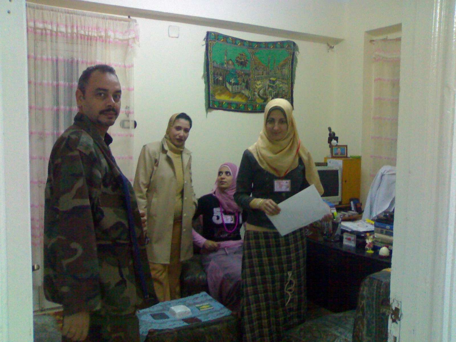 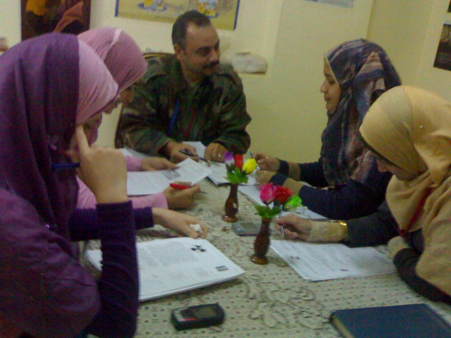 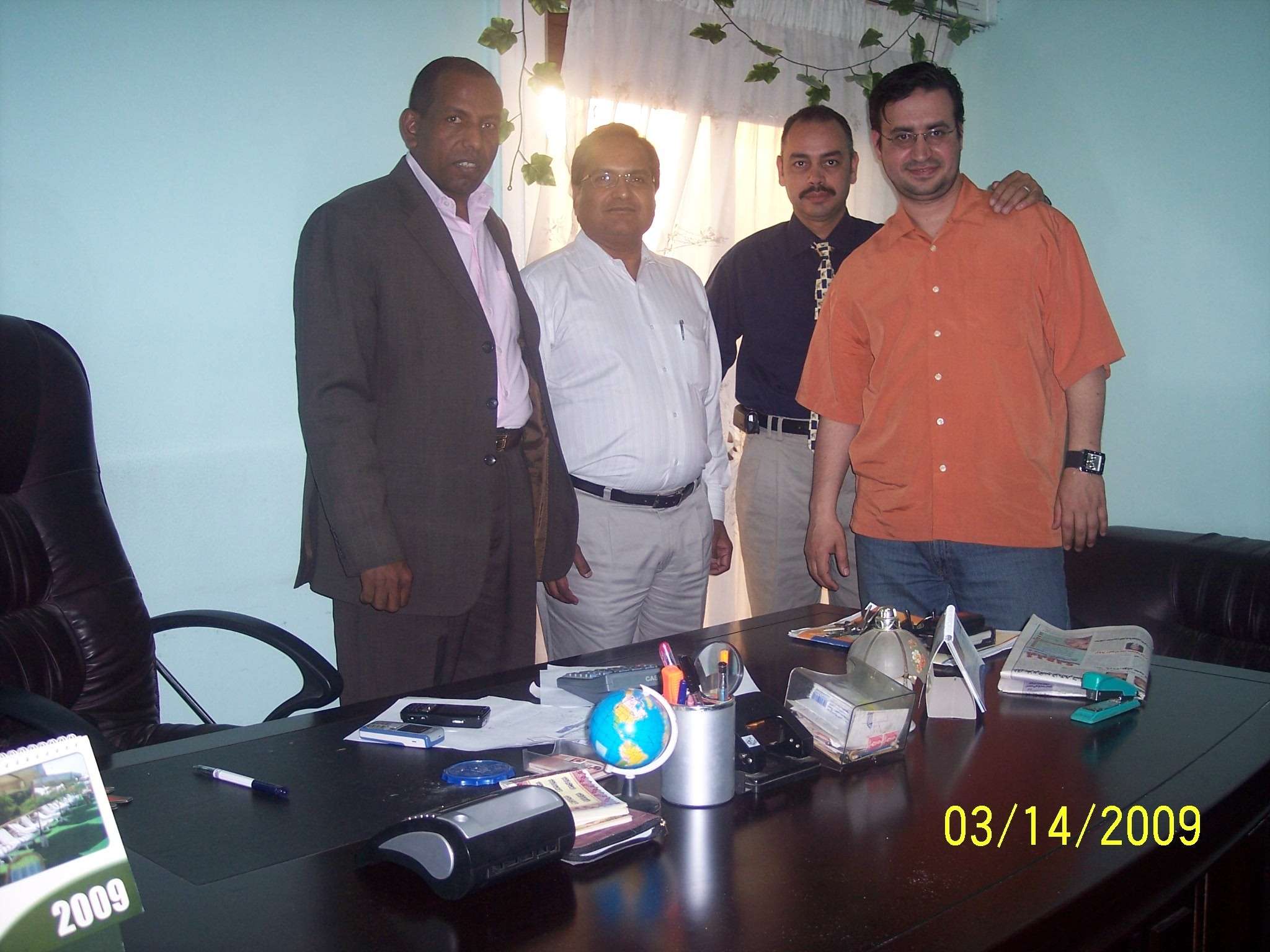 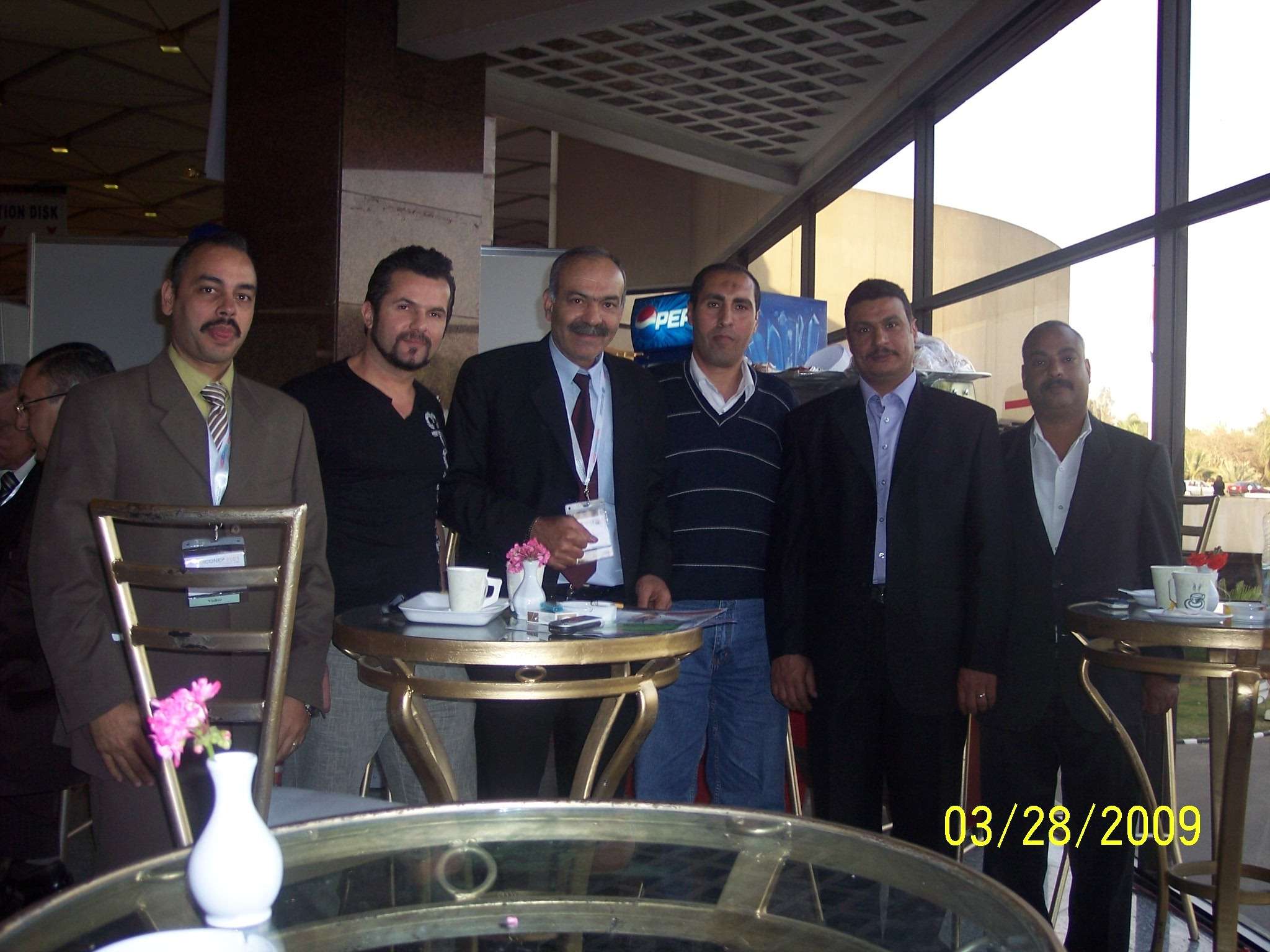  صور من وحدات معالجة المياه
 technolab el-bahaa group technolab el-bahaa groupTECHNOLAB EL-BAHAA GROUP
EGYPT
FOR
WATER
TREATMENT/PURIFICATION/ANALYSIS
CONSULTANTS
CHEMIST/PHYSICS/MICROBIOLIGIST
INDUSTRIAL WATER
WASTE WATER
DRINKING WATER
TANKS CLEANING
CHAIRMAN
COLONEL.DR
BAHAA BADR EL-DIN
0117156569
0129834104
0163793775
0174041455 تصميم وانشاء محطات صرف صناعى/waste water treatment plant design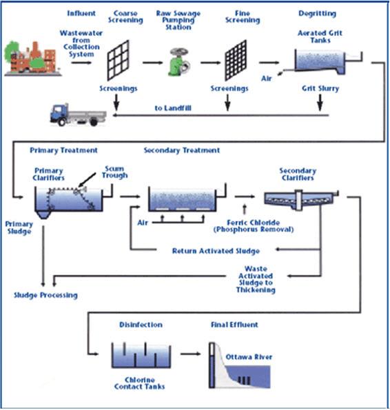 technolab el-bahaa group egypt We are a consultants in water treatment with our chemicals as:- Boiler water treatment chemicals Condensated steam treatment chemicals Oxygen scavenger treatment chemicals Ph-adjustment treatment chemicals Antiscale treatment chemicals Anticorrosion treatment chemicals Open cooling tower treatment chemicals Chillers treatment chemicals Waste water treatment chemicals Drinking water purification chemicals Swimming pool treatment chemicals Fuel oil improver(mazote/solar/benzene) technolab el-bahaa group
egypt
We are consultants in extraction ,analysis and trading the raw materials of mines as:-
Rock phosphate
32%-30%-28%-25%
Kaolin
Quartez-silica
Talcum
Feldspae(potash-sodumic)
Silica sand
Silica fume
Iron oxid ore
Manganese oxid
Cement(42.5%-32.5%)
Ferro manganese
Ferro manganese high carbon technolab el-bahaa group
web sites
e-mails
water treatment unit design 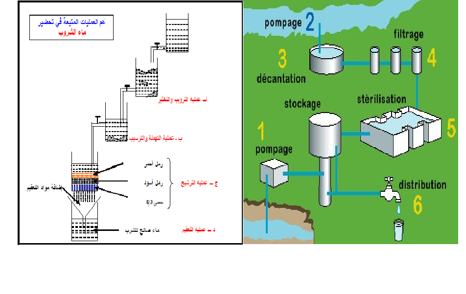
وكلاء لشركات تركية وصينية لتوريد وتركيب وصيانة الغلايات وملحقاتها
solo agent for turkish and chinese companies for boiler production/manufacture/maintance
وكلاء لشركات تركية وصينية واوروبية لتصنيع وتركيب وصيانة ابراج التبريد المفتوحة 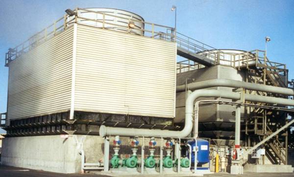
تصميم وتوريد وتركيب الشيللرات
design/production/maintance
chillers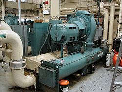 ابراج التبريد المفتوحة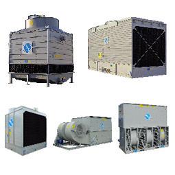 مجموعة تكنولاب البهاء جروب
المكتب الاستشارى العلمى
قطاع توريد خطوط انتاج المصانع
نحن طريقك لاختيار افضل خطوط الانتاج لمصنعكم
سابقة خبرتنا فى اختيار خطوط الانتاج لعملاؤنا
1)خطوط انتاج العصائر الطبيعية والمحفوظة والمربات
2)خطوط انتاج الزيوت الطبيعية والمحفوظة
3)خطوط انتاج اللبن الطبيعى والمحفوظ والمبستر والمجفف والبودرة
4)خطوط تعليب وتغليف الفاكهة والخضروات
5)خطوط انتاج المواسير البلاستيك والبى فى سى والبولى ايثيلين
6)خطوط انتاج التراى كالسيوم فوسفات والحبر الاسود
7)خطوط انتاج الاسفلت بانواعه
 محطات معالجة الصرف الصناعى والصحى بالطرق البيولوجية والكيميائية محطات معالجة الصرف الصناعى والصحى بالطرق البيولوجية والكيميائية9)محطات معالجة وتنقية مياه الشرب
10)محطات ازالة ملوحة البحار لاستخدامها فى الشرب والرى
11)الغلايات وخطوط انتاج البخار الساخن المكثف
12)الشيللرات وابراج التبريد المفتوحة وخطوط انتاج البخار البارد المكثف
للاستعلام
مجموعة تكنولاب البهاء جروب
0117156569
0129834104
0163793775
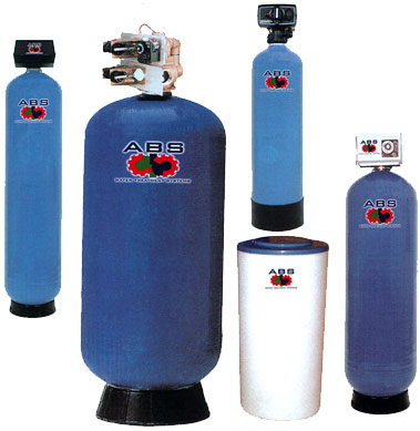
القاهرة-شارع صلاح سالم-عمارات العبور-عمارة 17 ب فلا تر رملية/كربونية/زلطيه/حديدية
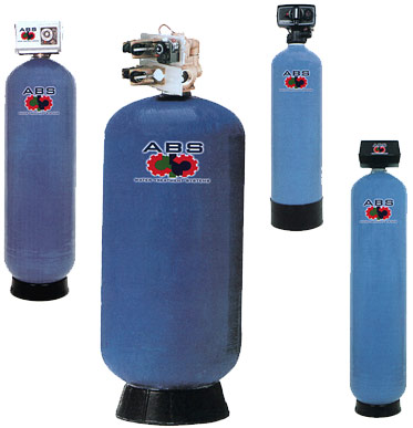
وحدات سوفتنر لازالة عسر المياه
مواصفات مياه الشرب
Drinking water
acceptable
values
50 | colour | acceptable | Taste | nil | Odour | 6.5-9.2 | ph |
1 mg/dl | pb | 5 mg/dl | as | 50 mg/dl | cn | 10 mg/dl | cd | 0-100mg/dl | hg | 8 mg/dl | f | 45 mg/dl | N02 | 1 mg/dl | Fe | 5 mg/dl | Mn | 5.1 mg/dl | Cu | 200 mg/dl | Ca | 150 mg/dl | Mg | 600 mg/dl | Cl | 400 mg/dl | S04 | 200 mg/dl | Phenol | 15 mg/dl | zn |
الحدود المسموح به
ا لملوثات الصرف الصناعى
بعد المعالجة
Acceptable
values
treated wate water
|
7-9.5 | ph | 25-37 c | Temp | 40 mg/dl | Suspended solid | 35 mg/dl | bod | 3 mg/dl | Oil & grase | 0.1 mg/dl | hg | 0.02 mg/dl | cd | 0.1 mg/dl | cn | 0.5mg/dl | phenol | 1.5 ds/m | conductivity | 200 mg/dl | na | 120 mg/dl | ca | 56 mg/dl | mg | 30 mg/dl | k | 200 mg/dl | cl | 150 mg/dl | S02 | 0.75 mg/dl | Fe | 0.2 mg/dl | Zn | 0.5 mg/dl | Cu | 0.03 mg/dl | Ni | 0.09 mg/dl | Cr | 0.53 mg/dl | لb | 0.15 mg/dl | pb |
محطات تحلية مياه البحر بطريقة التقطير الومضى على مراحل MSF+3.jpg (image)محطات التقطير الومضى لتحلية مياه البحر2![[MSF+3.jpg]](https://2img.net/h/4.bp.blogspot.com/_SynCnHGx75g/Shl2T3oVhsI/AAAAAAAAAEY/_7oem5pvQ3I/s1600/MSF%2B3.jpg) some of types of tanks we services
انواع الخزانات التى يتم تنظيفها
ASME Specification Tanks
Fuel Tanks
Storage Tanks
Custom Tanks
Plastic Tanks
Tank Cleaning Equipment
Double Wall Tanks
Septic Tanks
Water Storage Tanks
Fiberglass Reinforced Plastic Tanks
Stainless Steel Tanks
Custom / Septic
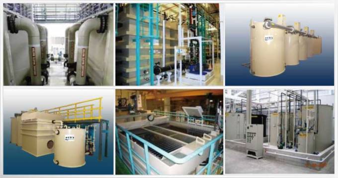
مراحل المعالجة الاولية والثانوية والمتقدمة للصرف الصناعى

صور مختلفة
من وحدات وخزانات معالجة الصرف الصناعى
التى تم تصميمها وتركيبها من قبل المجموعة
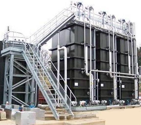
صور
من خزانات الترسيب الكيميائى والفيزيائى
لوحدات معالجة الصرف الصناعى
المصممة من قبل المحموعة
 technolab el-bahaa group
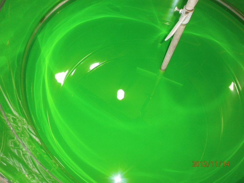
 technolab el-bahaa group technolab el-bahaa group technolab el-bahaa group technolab el-bahaa group technolab el-bahaa group technolab el-bahaa group technolab el-bahaa group technolab el-bahaa group technolab el-bahaa group technolab el-bahaa group technolab el-bahaa group technolab el-bahaa group technolab el-bahaa group technolab el-bahaa group technolab el-bahaa group technolab el-bahaa group technolab el-bahaa group technolab el-bahaa groupمياه رادياتير اخضر اللون
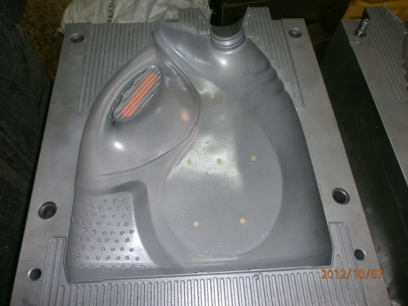
بريستول تو ايه
انتاج شركة بريستول تو ايه - دمياط الجديدة
مجموعة تكنولاب البهاء جروب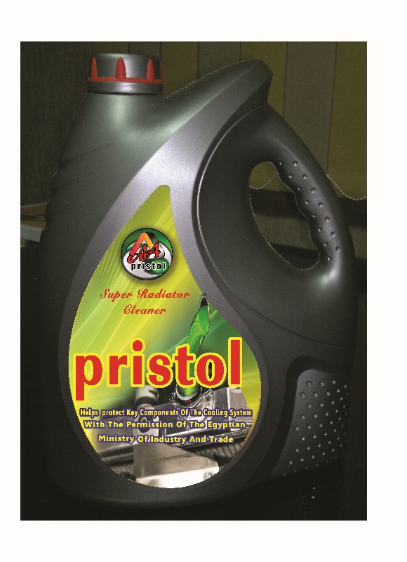
اسطمبات عبوات منتجات شركة بريستول تو ايه-دمياط الجديدة مياه رادياتير خضراء فوسفورية من انتاج شركة بريستول تو ايه بترخيص من مجموعة تكنولاب البهاء جروب 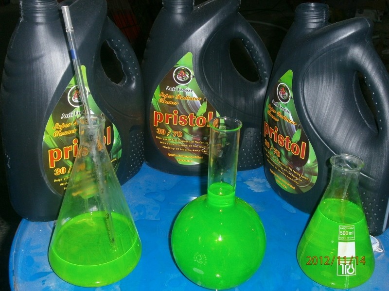

زيت فرامل وباكم DOT3 
|
|
| | منظومة تنظيف وغسيل وتطهير واعادة تاهيل الخزانات (النسخة الانجيليزية) |  |
| | | كاتب الموضوع | رسالة |
|---|
Admin
Admin

عدد المساهمات : 3762
تاريخ التسجيل : 15/09/2009
العمر : 57
الموقع : مصر
 |  موضوع: منظومة تنظيف وغسيل وتطهير واعادة تاهيل الخزانات (النسخة الانجيليزية) موضوع: منظومة تنظيف وغسيل وتطهير واعادة تاهيل الخزانات (النسخة الانجيليزية)  السبت يونيو 04, 2011 11:14 am السبت يونيو 04, 2011 11:14 am | |
| Water main disinfection of water tanks
The purpose of water mains disinfection is to eliminate all kind of contamination that can occur during construction and during storage of pipes and pipe accessories.
Contaminations will greater impact whenever pipes extremities are not well plugged.
Reducing the potential sources of contamination in the new or repaired pipe will enhance the effectiveness of the disinfection process.
The first step of the installation procedure to reduce contamination risk is to keep the pipe as clean as possible before it is installed and placed into service.
No disinfecting agent can be efficient
when pipes contain sediments that serve as a habitat for micro-organisms.
They therefore need to be properly cleaned before disinfection.
Mains cleaning
The main shall first be thoroughly flushed in sections through hydrant or wash outs with sufficient volume and velocity of water to remove all foreign matter.
The flow of water shall be from one direction at any time, and depending on the position of the flushing point (s), flushing may be required alternatively from opposite directions to ensure all of the unsafe water is completely flushed out of the main.
Following successful flushing, the main shall be chlorinated.
Levels of Disinfection
In practice, after mains cleaning (item 3.1.4), the main is still full of water and therefore shall be drained completely, then slowly filled with potable water that has been premixed with sufficient free chlorine to produce a uniform concentration of between 20mg/L and 50mg/L in the main (test required).
The chlorinated water shall be introduced at the lowest point of the section of the main to be disinfected to ensure no air is trapped. While in contact with chlorinated water, all valves, hydrants and other fittings on the section shall be operated at least once to allow the chlorinated water to pass through them and under valves seats etc. then closed.
The main shall then be left full of this chlorinated water for 24hours.
After 24 hours the residual chlorine concentration must not be less than 10mg/L(test required).
If this requirement is not achieved, the chlorination procedures shall be repeated.
If this disinfection requirement is achieved, the higher chlorinated water in the main and service connection pipes shall then be flushed out and dechlorinated before discharging into storm water system, wastewater system or receiving waters.
The flushing shall continue until the chlorine concentration inside the water main is less than or equal to 0.5mg/L (test required).
Following a successful chlorination procedure, the main shall be tested for the presence of micro-organisms.
The water used for flushing must be potable and may be applied by:
● connecting to a live water main, with approved backflow device.
● a water tanker filled with potable water.
(the water tanker must be sterilised with 25mg/L of chlorine for 12 hours, dechlorinated and disposed of appropriately, inside of tank cleaned out before use)
The desired level of chlorine concentration, ranging from 20mg/L to 50mg/L, is
produced by thoroughly mixing sodium hypochlorite (NaOCl) with clean water in a
clean tanker, to the proportions indicated in the table below.
Under No circumstances will the use of handful of hypochlorite powder, granules
by
colonel.dr
bahaa badr
chemical consultant
| |
|   | | Admin
Admin

عدد المساهمات : 3762
تاريخ التسجيل : 15/09/2009
العمر : 57
الموقع : مصر
 |  موضوع: : منظومة تنظيف وغسيل وتطهير واعادة تاهيل الخزانات (النسخة الانجيليزية) موضوع: : منظومة تنظيف وغسيل وتطهير واعادة تاهيل الخزانات (النسخة الانجيليزية)  السبت يونيو 04, 2011 11:22 am السبت يونيو 04, 2011 11:22 am | |
| tablets dumped into the pipe or hydrants tee be acceptable practice
The desired level of chlorine concentration, ranging from 20mg/L to 50mg/L, is produced by thoroughly mixing sodium hypochlorite (NaOCl) with clean water in a clean tanker, to the proportions indicated in the table below.
Mains diameter(mm) = ( 50/100/150/200/225)
Volume of water (L) per /100m length of main = (196.35/785.4/1767.0/3141.6/3976.0)
Required volume(mls) of 12.5% NaOCL to produce 20mg/L dose = (31.5/125.5/282.5/502.6/636.2)
Required volume(mls) of 12.5% NaOCL to produce 50mg/L dose = (78.5/314.2/706.8/1256.4/1590.5)
Methods of introducing chlorine solution into mains.
The introduction of chlorine will primarily depends on the volume of the particular main and the availability of appropriate equipment
In general, wherever the pipe volume is less the 10m3, the most appropriate method is to add the required amount of chlorine solution to a potable water tanker suitable for carrying potable water to achieve the desired dose rate (mg/L as FAC).
This may require more than one water tanker.
For greater quantities, the chlorine solution may be injected into the main using the flow proportional dosing method.
An approve backflow device must be installed when using live water main for the purpose of filling the main with water.
Appendix C describes an approved method of dosing the chlorine.
Testing the success of disinfection
conduct the following on-site tests using random samples from a selection of the bleed points:
● Check for a clean and clear sample in a transparent container against a white background.
● Test for free available chlorine concentration (FAC) from all samples.
● Test for pH from one of the samples using the procedures detailed in Appendix B.
Note that higher pH values reduce the effectiveness of the applied chlorine.
● Test for turbidity value from all samples
De-chlorinating and Discharging chlorinated Water.
Discharging of higher concentrated chlorinated water to waste shall be undertaken to minimise the potential damage to equipment but primarily to storm water system, wastewater system and receiving waters.
There are several methods of de-chlorinating and flushing out the higher chlorinated water from the water-main and discharging appropriately.
Water Tanker
Draining out the main and transferring to a water tanker, applying dechlorinating agent, test to ensure FAC to be less then or equal to 1.0mg/L before discharging.
Flow Proportional Dosing
Pre mix the de-chlorinating agent into a solution tank and dose (using a dosing pump) flow proportionally when draining out the chlorinated water from the main.
The water must be mixed well to allow even distribution of the de-chlorinating agent to chlorinated water before discharging
Note:
1. Higher chlorinated water of more then 1.0mg/L shall not be discharged onto the ground or into any storm water drain.
2. If a dosing pump is available to treat and neutralise the chlorinated water
Final Flush of Mains
Once the chlorinated water is correctly disposed of, any remaining hook-ups to the live system shall be completed by the ALC.
The ALC shall thoroughly flush the entire new system with fresh water from the live mains for at least 10 minutes or until it is clean and clear in a container against a white background
Flushing shall be from hydrants and the bleed points at the extremities of the smaller diameter pipelines.
Microbiological test of newly livened systems
Within 12 hours of the new watermain being livened, the Client’s representative shall collect one random sample of water for microbiological testing.
A bleed point with a closed gate valve shall be clearly identified for the sampler to use if no hydrant is
available.
The sample, to be collected and tested at the expense of the Client and shall be tested for E-coli, Total Coliform, Heterotrophic Plate Count, chlorine, pH and turbidity.
The new pipelines are deemed to have passed the microbiological test if:
● The E-coli result is 0/100mL
● Total Coliform result is 0/100mL and
● Heterotrophic Plate Count result is less than 10 cfu/mL.
When completed, all temporary bleed points are plugged off at the tapping on the main.
If the Heterotrophic Plate Count fails, the contractor shall flush the water immediately upon notification from Western Bay of Plenty District Council and repeat the microbiological tests.
If the E-coli test fails, the contractor shall follow the procedure, as directed by the Council’s Representative
by
colonel.dr
bahaa badr
chemical consultant.
| |
|   | | Admin
Admin

عدد المساهمات : 3762
تاريخ التسجيل : 15/09/2009
العمر : 57
الموقع : مصر
 |  موضوع: منظومة تنظيف وغسيل وتطهير واعادة تاهيل الخزانات (النسخة الانجيليزية) موضوع: منظومة تنظيف وغسيل وتطهير واعادة تاهيل الخزانات (النسخة الانجيليزية)  السبت يونيو 04, 2011 11:32 am السبت يونيو 04, 2011 11:32 am | |
|
Disinfection of Existing main
General Conditions
This contract work requires work on existing mains while they are in service, including the installation, replacement and removal of fittings during connection of new mains and disconnection of redundant mains.
The contractor shall follow the disinfection procedures outlined below:
To prevent ingress of contamination through the failed pipe, draining water mains
through hydrants shall only be done where all of the section of pipe being drained is fully intact, i.e.. where the pipe has no cut or broken areas.
Water mains that have been cut or broken shall only be drained through the cut or broken area (e.g. where a piece of pipe has been removed to install a branch tee), while the level of the wastewater in the trench is kept well below the cut area of the pipe.
The disinfection of repaired mains depends on the risk criteria and is explained with appropriate action.
Low Risk Situations
Low risk situations are where the pressure in the pipe is maintained while carrying out work which involves cutting or tapping into the live main (e.g. installing service connection, or a branch connection using live tapping techniques) The procedure shall be:
• Spray all surface of fittings and the exterior of the watermain with 5% chlorine solution e.g. undiluted household bleach liquid.
Medium Risk:
Medium risk situation are where the pressure in the pipe is removed by controlled draining of the pipe into the trench excavation under the point where the pipe is cut, but no external liquid or solid material makes any contact at all with the pipe's interior, i.e.. little possibility of contamination (e.g. cutting in a branch tee where the trench is thoroughly dewatered) The procedure shall be:
• Spray all surfaces of fittings, and the interior of both open ends of the water main with 5% chlorine solution.
• After completion of the work, flush the water main out through hydrants on either end of the break for a minimum of 3minutes.
High Risk
High-risk situations are where any external liquid or solid material has made contact with the cut area of the pipe or has entered the pipe fittings, i.e.. contamination has occurred. The procedure shall be:
• Inform the Engineer when the situation arises
• Isolate the watermain to prevent further travel of the contaminated water.
• If practical, also isolate all affected service connections
• If the excavation is badly contaminated, apply liberal amount of HTH powder or granules or use the spray bottle to spray around the affected areas to reduce the risk of contamination.
• Drain the watermain through the cut section while keeping the trench water level well below the level of the cut pipe.
• While maintaining this water level in the trench, flush as much of the contaminated material as possible from the water main through the cut area by opening valves at either end of the reticulation system.
• After completion of work, follow the disinfection procedure; by shock dosing the main using a water tanker filled with predetermine chlorine strength or dosing flow proportional and leave the chlorinated water inside the water main for 24 hours.
• Follow the chlorination, Bacteriological and Disposal of super-chlorinated water procedures.
by
colonel.dr
bahaa badr
chemical consultant
| |
|   | | Admin
Admin

عدد المساهمات : 3762
تاريخ التسجيل : 15/09/2009
العمر : 57
الموقع : مصر
 |  موضوع: منظومة تنظيف وغسيل وتطهير واعادة تاهيل الخزانات (النسخة الانجيليزية) موضوع: منظومة تنظيف وغسيل وتطهير واعادة تاهيل الخزانات (النسخة الانجيليزية)  السبت يونيو 04, 2011 11:45 am السبت يونيو 04, 2011 11:45 am | |
| REPAIRS MAINTAINED UNDER POSITIVE PRESSURE:
All the criteria for chain of cleanliness and workers hygiene are followed and the pipe is to be maintained under positive internal water pressure until all soil and trench water is removed from the section to be repaired.
Care should be taken in keeping the leak under positive pressure requires, that, there shall be no opportunity for contaminated ground or trench water to have entered the reticulation.
Additionally, the leak should be small enough so that it is unlikely that backflow conditions will have been created elsewhere by the head loss due to high flow through the leak.
This would generally apply to a small sized leak where there was no possibility of the flow going back into the system.
Following the repair the main and consumers connections adjacent to the repair are to be thoroughly flushed.
REPAIRS WHERE LOSS OF PRESSURE OR BACKFLOW
CREATING CONDITION HAVE OCCURRED
a) Make sure that hygienic work practice and the chain of cleanliness is observed.
b) Isolate section of main and drain through break if possible keeping trench water and debris from entering the pipe
c) Apply chlorine solution to trench walls; pipes and fittings, remove any accessible debris which has entered the pipe; and make the repair.
d) Fill the pipe with a pre-determine dose, preferably a 50mg/L of chlorinated water from remote source (water tanker).
e) Allow 2hours for contact time
f) Drain out and pumped into tanker for de-chlorination prior to discharging
g) Flush the main with potable water by opening valves from both ends of pipe.
h) If the repair is of such urgency, or, for other reasons, disinfection is not possible, then all attempts should be made to prevent ingress of contaminants;
any materials having entered the main should be removed if possible and, following the removal of this material; the accessible areas of the pipe exterior;
interior and fittings thoroughly cleaned with chlorine cleaning solution.
This main should then be again chlorinated, flushed and recommissioned.
i) Undertake post repair bacteriological sampling on a random basis for low contamination risk situations, and mandatory for all other cases.
Making Chlorine Cleaning Solution
The chlorine cleaning solution to be used should be at a strength not greater then10%.
This can be made by diluting the sodium hypochlorite solution (12.5% available chlorine)
This can be made by mixing and or diluting the Sodium hypochlorite into a clean potable water.
The table below gives you a guide to preparing various volumes with commercial strength sodium hypochlorite.
The procedure to correctly mix the chlorine solution is:
1. Select the volume required,
2. Fill the container with 2/3 water,
3. Add the volume of sodium hypochlorite off the chart,
4. Then top up the water and mix for 1 minute.
Following mixing, take a sample to test to ensure that the level of FAC is to your requirement. If it is not, add more chlorine solution until it is.
Required Volume of Solution (L)
12.5% Sodium Hypochlorite
(L) 1% 3% 5% 10%
1 80mls 240mls 400mls 800mls
10 800mls 2.4L 4.0L 8.0L
20 1.6L 4.8L 8.0L 16.0L
50 4.0L 12.0L 20.0L 40.0L
100 8.0L 24.0L 40.0L 80.0L
200 16.0L 48.0L 80.0L 160.0L
1000 80.0L 240.0L 400.0L 800.0L
Chlorination of Mains using a Dosage Pump Setup
The main to be dosed is likely to be completely or partly full of water following the flushing to remove dirt and large items, and, the pressure testing.
The procedure is therefore as follows:
1. Select the chlorine concentration needed to give the CT values required by the code of practice.
This will be governed by the available time for the chlorinated water to sit in the pipe.
For new mains, given that 3 days will normally be used, (24 hour contact and 2 days for the return of the microbiological testing results), the dose rate usually starts from 20g/m3.
2. Add a further 10g/m3 or more to the dose rate selected (This is to allow for some loss of chlorine strength during the contact period).
This is the dose rate to apply.
For new mains this will now normally be 30g/m3 (20 + 10).
3. Set up the dosing rig so that the main is being fed from a remote hydrant and if possible the water is being fed into the low end of the main.
A hydrant or bleed line should be opened in the upper remote end of the main to release air and water while the filling occurs.
With the dosing rig set up and connected, measure the flow rate on the flow meter.
We are aiming for100L/min.
This should be done over a period of 1 minute.
4. Using the formula and calculation below, work out the required dosing pump flow rate.
Pump flow rate = Cl2 dose required x above flow rate x 60 ÷10,000♦(L/hr) (g/m3) (L/min) (min/hr)
* Use the factor of 10,000 if a 1% chlorine solution is used.
If a different strength solution is used then divide by solution strength (% x 10,000) = g/m3
5. Check the chlorine dosing pump stroke setting is at maximum (100%) and select the speed setting to give the flow rate required as calculated in step 4 above using the pump calibration graph.
Turn the pump on and ensure that it is working.
If no flow from the chlorine container is evident, you may need to prime the pump.
(Follow pump manufacture’s instruction) NOTE: Ensure you are wearing the safety equipment (goggles, gloves, overalls and boots), any time you are working on the dosing pump or lines.
6. Operate the rig until the super-chlorinated water comes out the drain line at or above the required chlorine level calculated in step 2.
The approximate time in minutes that this will take can be calculated from the formula:
Time (min) = Πr2 x L x 1000 Q
where: r2 = pipe radius in metres, e.g. 150mm pipe diameter ÷1000 ÷2 = 0.075m
L = length between hydrants or finish points in metres, usually 90m for adjacent hydrants
Q = Rig flow rate calculated in Step 3 above, in L/min.
Thus, a 90m length of 100mm pipe filling at 100L/min should take 7 minutes; a 90m length of 150mm pipe should take 16 minutes and a 90m length of 200mm pipe 28 minutes.
7. Flush out any service connections with the super-chlorinated water then with the main fill to the required level, shut off the dosing pump and rig.
8. Leave the main for the time period selected in step 1 (for new mains usually24 hours).
9. At the sampling locations discharge the chlorinated water for at least 1 minute, collect the required microbiological sample and leave the valve closed.
10. Testing of the sample shall be in accordance with clause 3.1.9 of the Disinfection Code.
11. Discharge of the chlorinated water from the main shall be in accordance with clause 3.1.7 of the Disinfection Code.
12. Final flushing of the new main shall be in accordance with clause 3.1.8 of the Disinfection Code.
13. Once the chlorination rig is finished with, run some clean water through the dosing pump to stop the build up of precipitates in the lines and fittings.
Neutralising Chlorine
The most common chemical used to neutralise chlorine after disinfecting mains
is sodium thiosulphate
So when preparing Sodium Thiosulphate solutions, the following steps should be taken:
1. Fill the solution tank approximately 2/3 full with water.
2. Add the required amount of sodium thiosulphate – 99% into the tank as per the table below to obtain a 15% w/v Na2SO3 solution.
Solution Volume (L) Sodium Thiosulphate to add (kgs)
10 1.5
20 3.03
30 4.5
40 6.0
50 7.6
100 15.2
200 30.3
300 45.5
400 61.0
500 76.0
800 121.2
1000 151.5
Amount of Na2SO3 (anhydrous) or Na2SO3.7H2O to add to obtain a 15% w/v Na2SO3solution.
3. Mix the solution until the sodium thiosulphate has dissolved.
4. Add the remainder of water and mix.
5. Stir periodically to prevent the solution stratifying.
The calculation below shows the amount of sodium thiosulphate (15% w/v solution)
to add to dechlorinate the available chlorine residual by flow proportionally dosing.
The flow rate of the 15% sodium thiosulphate solution is calculated in the following manner:
Flow (L/hr) = FAC (g/m3) x 3 x draining flow rate of chlorinated water (L/min) x 60min/hr
Sodium Thiosulphate strength (%) x 10,000.
For example,
The FAC of water to be discharged is 10g/m3 and it is being discharged at a flow rate of 100L/min.
With a ration of 3:1, what is the required flow rate of 15% sodium thiosulphate in L/hr?
Flow = 10g/m3 x 3 x 100L/minx 60min/hr = 1.2L/hr 15% x 10,000
● A calibrated dosing pump will enable this flow to be achieved by adjusting the speed or stroke setting off a calibration chart.
● A check on the treated water FAC level will ensure that the dose is adequate.
● After 10 seconds contact time the FAC level should be close to 0.
by
colonel.dr
bahaa badr
chemical consultant | |
|   | | Admin
Admin

عدد المساهمات : 3762
تاريخ التسجيل : 15/09/2009
العمر : 57
الموقع : مصر
 |  موضوع: منظومة تنظيف وغسيل وتطهير واعادة تاهيل الخزانات (النسخة الانجيليزية) موضوع: منظومة تنظيف وغسيل وتطهير واعادة تاهيل الخزانات (النسخة الانجيليزية)  السبت يونيو 04, 2011 11:50 am السبت يونيو 04, 2011 11:50 am | |
| Disinfection Process Summary – Flow Chart
- Flush loose deposits until clean
- Apply chlorine solution: 10 - 30mg/L FAC Contact time of 24 hrs
- Onsite FAC & pH tests done by approved contractor:
- Fail= Repeat the process
- Pass=Discharge FAC appropriately
- Fill main with town supply and test for FAC until expected town supply
value for FAC is reached.
- Microbiological sample collected by approved Contractor staff for testing.
- Total Coliform (TC)
- Faecal Coliform (E-Coli)
- Hetratophic Plate Count (HPC)
- E-Coli failure=Advice the Council's representative of the presence of E-Coli
- HPC failure = Advice the Project Manager& Council's representative and repeat process from item 6
- Pass=End of process.
- Forward all documentations to Council's representative, including producer statement on disinfection process & results obtain.
- Project File to Records
by
colonel.dr
bahaa badr
chemical consultant | |
|   | | | | منظومة تنظيف وغسيل وتطهير واعادة تاهيل الخزانات (النسخة الانجيليزية) |  |
|
مواضيع مماثلة |  |
|
| | صلاحيات هذا المنتدى: | لاتستطيع الرد على المواضيع في هذا المنتدى
| |
| |
| |
|


![[MSF+3.jpg]](https://2img.net/h/4.bp.blogspot.com/_SynCnHGx75g/Shl2T3oVhsI/AAAAAAAAAEY/_7oem5pvQ3I/s1600/MSF%2B3.jpg)


