Admin
Admin

عدد المساهمات : 3762
تاريخ التسجيل : 15/09/2009
العمر : 57
الموقع : مصر
 | موضوع: وحدات فصل الزيوت عن المياه الصناعية/API Separators - The Workhorse of Refinery Wastewater Treatment Systems  الأربعاء فبراير 22, 2012 3:33 am الأربعاء فبراير 22, 2012 3:33 am | |
| API Separators - The Workhorse of Refinery Wastewater Treatment Systems
BY
GENERAL.DR
BAHAA BADR
TECHNOLAB EL-BAHAA GROUP
Proper design and selection of support equipment, and understanding issues affecting API separators are very important to the efficiency of this key piece of refinery wastewater treatment equipment.
The following article discusses all of these issues.
Compiled From
Introduction
The API Separator is normally the first, and arguably most important, wastewater treatment step in most petroleum refineries.
For years, refineries have attempted to use other technologies or treatment scenarios as an alternative to the API separator.
But most refineries ultimately select, or return to, the API separator as the technology of choice for their wastewater treatment primary oil/solids separation step.
The primary function of a properly designed API separator is to remove gross quantities of oil and suspended solids from refinery wastewater prior to subsequent downstream wastewater treatment processes
– normally a second oil/water separator polishing step and some form of advanced treatment for removal of dissolved organic compounds (typically biological treatment, though other treatment technologies have been used).
The API separator was developed over 70 years ago in a joint effort by The American Petroleum Institute (API) and Siemens Water Technologies Envirex Products (then Rex Chain Belt).
The first API separator was provided in 1933 to Atlantic Refining’s Philadelphia refinery, and since then, hundreds of refineries around the world have installed API separators in their wastewater treatment plants.
How it Works
The API separator is a gravity separation device that works on the principle of Stokes Law, which defines the rise velocity of an oil particle based on its density and size.
Typically, the difference between the specific gravity of oil to be separated and water is much closer than the specific gravity of the suspended solids and water.
Therefore, the design of the API separator is based on the difference in the specific gravity of the oil to be separated and the wastewater.
If this design criterion is followed, the majority of suspended solids will settle in the unit.
Once the oil and suspended solids are removed from the wastewater in the API separator, the middle phase, water, is then sent on for further treatment in most refinery wastewater treatment plants.
Design Standards
Through the original work done by the American Petroleum Institute and us in the 1930s, and numerous subsequent improvements, the design standards for the API separator have been well documented and can be found in the current edition of API Specification 421.
Some of the most important design criteria developed for API separators include:
• Length to width ratio. A minimum length to width ratio of 5:1 is recommended for all API separator designs to keep operating conditions as close to plug flow as possible, minimizing the potential for short circuiting.
• Depth to width ratio.
A minimum depth to width ratio of 0.3 to 0.5 is recommended so that separation units are not excessively deep, minimizing the amount of time it takes for oil particles to rise to the surface.
• Maximum channel width and depth.
The maximum API separator channel width is 20 ft; maximum depth is 8 ft.
• Horizontal velocity. Maintaining a horizontal velocity of no more than 3.0 ft/sec has been shown to minimize turbulence and its effect on interfering with the separation of oil from wastewater.
• Inlet distribution.
To minimize the effect of high wastewater inlet velocities into the API separator, and possible short circuiting associated with these high velocities, reaction jet baffles are recommended to diffuse influent flows across the width and depth of the API separator.
• Oil particle size. Majority of oil particles in most refinery wastewaters are 150 micron in size or larger.
Therefore, the design standards for API separators were developed for the removal of oil particles of this size.
Particles smaller than 150 micron will normally exit an API separator and will need to be removed by downstream treatment processes, unless allowances are made in the sizing of the API separator to remove these smaller particles.
Design Features
In addition to the previously mentioned Design Standards, there are certain features which should be considered in any API separator design to insure efficient treatment and environmental compliance, with minimal operator attention.
Some of these are as follows:
• Incorporating a single scraper/skimmer system in the tank to remove settled solids and floating oil to maintain optimum capacity in the separator.
The scraper/skimmer system usually consists of a four shaft, chain and flight collector system that conveys settled solids to a sludge hopper at the inlet end of the unit, and floating oil to a skimmer at the effluent end of the unit.
• Providing some method to remove accumulated oil from the surface of the API separator.
This is usually a rotating oil skimmer pipe, but may also include an oil roll skimmer. Electronic or manual monitoring of the oil level in the API separator tankage may also be incorporated into the design.
• Methods to continuously or intermittently remove accumulated solids (sludge) from the API separator, usually including some type of sludge pumping system.
• A method to transfer (pump) wastewater to the separator if gravity flow is not possible (as with above-grade API separator tanks).
• Wastewater inlet distribution system/dispersion system.
• Installing air-tight covers for VOC/vapor containment, which usually includes some type of inert gas blanketing system for safety.
• Using above-ground steel tanks to contain potentially hazardous wastE sandwastewaters, 2.
Myth vs. Fact
The major fallacies of API separator performance are: that they will always remove a certain percentage of oil and TSS in a wastewater; or that they should always achieve a certain effluent quality, independent of influent oil and TSS concentration.
In reality, the typical performance of an API separator in a petroleum refinery and illustrates how a properly designed API separator should operate.
A well-designed API separator should achieve effluent oil and TSS concentrations of 50 to 200 mg/l, independent of influent concentration, to ensure protection and proper operation of downstream treatment processes.
As the graph shows, effluent quality from this API separator is fairly consistent, even if the influent quality is highly variable.
Selecting Proper Support Equipment is Key
While the design of the API separator seems simple enough, we know that doing a textbook design for an API separator and actually operating an API separator are two different things.
Designing an API separator to operate properly is more than running a sizing calculation. The separator must not only be properly sized, but the equipment that supports the operation of the API separator must be properly designed.
Think of an automobile engine—the best one in the world will fail if the components that support its operation are not properly designed and selected.
The same is true for an API separator.
To operate as designed, all support equipment needs to function properly, including raw wastewater pumping systems (if used), sludge pumping/removal systems, sludge collector systems, VOC/vapor containment systems and oil collection/removal systems.
Raw Wastewater Pumping
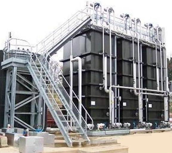
Many new API separators are now located in above-grade steel tanks, allowing for easy inspection and maintenance.
In some cases, this means that raw wastewater must be pumped to the separator; however, pumping action can shear and emulsify oil droplets, adversely affecting oil removal efficiency in the separator and impacting performance of downstream wastewater treatment processes.
Therefore, select a pump that is low shear and low turbulence to minimize oil particle shear and emulsification—an Archimedes screw pump is ideal for this application.
Sludge Pumping/Removal Systems
Arguably the most important support equipment in API separator design, sludge pumping/removal systems remove accumulated oily sludge from the separator.
If not removed, internal chain and flight collector components will likely fail from being overloaded by excessive sludge volumes.
In fact, lack of effective sludge removal is the most common reason API separators do not operate properly.
When designing a sludge removal system, consider the following:
• API separator sludge is heavy, viscous and sticky, and can quickly bridge in sludge
hoppers, plugging sludge withdrawal points. Fluidize and break up compacted sludge by using nozzles and water or steam in the sludge hoppers.
• Use clean-out and flushing connections on the sludge withdrawal piping to keep piping from plugging.
• Positive displacement, diaphragm pumps have been used successfully in separator sludge pumping applications.
Centrifugal trash pumps have also shown some success here.
• Locate sludge pumps close to, and at the same elevation as, sludge hoppers to provide flooded suction to the pumps and minimize sludge suction piping, which is prone to plugging.
Sludge Collector Systems
Chain and flight collector systems installed in API separators serve two purposes:
• To skim floating oil to a common collection point
• To scrape settled oil solids to a common withdrawal point
If floating oil and settled solids are allowed to collect and accumulate in the separator, its effective volume will decrease, affecting oil and solids removal efficiency which will be noted as increased oil and suspended solids concentrations in the effluent from the separator. This can adversely affect downstream treatment processes.
VOC/Vapor Control Systems
In most cases, API separators in petroleum refineries or petrochemical plants need to be provided with one of two types of covers for VOC containment/control:
• Floating covers—float on the surface of the separator
• Fixed covers—set above the surface of the separator
Consider the following for proper cover selection:
• Oil skimming efficiency/interference with oil skimming
• Ease-of-access to, and maintenance of, collector components
• Safe operation
• Capital and operating cost
• Regulatory compliance
• Maintenance requirements
Both fixed and floating cover systems have been used often and successfully.
Note that floating covers can interfere with oil skimming devices that extend above the water surface at the effluent end of the separators.
Fixed covers must be used over these components even if the remaining portion of the separator uses floating covers.
In general, fixed covers are more commonly used on new API separators and floating covers are generally used when existing separators must be covered for VOC control.
Interestingly, covering API separators has significantly impacted the process of oil removal from separators.
It is difficult, if not impossible, to see into a covered separator to determine oil levels and skimming needs, resulting in oil not being removed often enough, causing oil carryover to downstream treatment processes, or oil being skimmed too often, resulting in significant amounts of water being skimmed with the oil.
While windows in the covers have helped, more successful solutions have included the installation of electronic probes in the separator covers to monitor oil concentration at various depths in the units, or the installation of sample taps on the side of the units (for above-grade separators) to manually monitor oil depth.
Oil Collection/Removal Systems
Oil collection is key to API separator design.
Removing oil from the separator will prevent accumulation and entrance into downstream treatment processes, but removal also allows for collection, recovery and reprocessing of the oil.
Typically, oil skimmer pipes are used for oil removal. These slotted pipes extend partially into the API separator at the effluent end.
Chain and flight collectors skim oil, which has accumulated on the surface of the separator, from the influent end to the effluent end of the unit. The skimmer pipe is rotated to begin skimming the oil.
To improve the quality of the skimmed oil (i.e., making sure it does not contain too much
water), many API separators also use an oil roll skimmer in addition to the skimmer pipe.
The oil roll skimmer is a drum that extends across the width of the separator, normally of metallic construction, and partially submerged in the surface of the wastewater.
The oil roll skimmer contains an external drive, which rotates the drum. As the drum rotates, free oil adheres to the specially prepared surface of the drum, and a doctor blade removes the accumulated oil from the surface of the skimmer as it rotates.
The oil then flows into a collection trough and out of the unit. Oil collected by an oil roll skimmer is usually 95 percent pure oil and is easily reprocessed. However, the capacity of oil roll skimmers is limited.
Upsets resulting in large amounts of oil entering sewer systems can quickly overload oil roll skimmers, which is why an oil skimmer pipe is always used as a backup oil removal device.
Oil roll skimmers will also not remove floating debris and paraffins, which may be present.
Beyond the systems and components that comprise the design of an API separator, there are issues to be aware of regarding process operations in petroleum refineries and petrochemical plants which can affect the operation and effectiveness of API separators, including changes in crude oils, the presence of emulsions and spent caustic being sent to the separator.
Operational Issues Can Affect Separator Efficiency
Many API separators being used today were designed and installed 20 to 40 years ago, or more.
At that time, many refineries processed much lighter crude oils than they do today. Obviously, the separator was designed accordingly.
As crude slates have become heavier, the oil contained in the wastewater entering API separators have also become heavier and closer to the specific gravity of water.
Therefore, it takes longer for the oil to separate by gravity from the wastewater and the efficiency of the separator may have decreased, sometimes significantly.
To offset this, some refineries today have taken major steps to reduce water usage at their facilities, which has reduced wastewater flow rate, thereby allowing more time in API separators for heavier oil particles to separate. However, designs of units installed many years ago should be reviewed to ensure adequate protection of downstream treatment equipment.
Oil Emulsions
One of the biggest problems facing existing API separators in petroleum refineries is the presence of oil emulsions in the wastewater.
API separators are gravity separation devices, typically designed to remove free oil particles larger than 150 micron in size. Anything that increases the amount, or percentage, of sub-150 micron oil particles (which includes formation of oil emulsions) can significantly impact the efficiency of API separators.
Two common operational issues can impact the size of oil particles, or cause oil emulsions – desalter brine water and spent caustic.
Desalter Brine Water
Many refinery desalters were originally designed to process lighter crude oils.
As these lighter crude oil slates become scarce, more refineries are processing heavier crude oils.
This has resulted, in many cases, in poorer separation of water from oil in the desalter and formation of oil emulsions.
In many petroleum refineries, the desalter brine water now contains significant amounts of oil and oil emulsions, which can quickly overwhelm API separators (and other oil/water separation equipment) in wastewater treatment plants.
In these cases, it may be worthwhile to provide a dedicated oil/water separation step for just the desalter brine water to break any oil emulsions and remove the majority of free oil before the brine water is sent to sewer.
This can prevent overloading the wastewater treatment plant API separators with oil and consequently affecting downstream treatment processes.
Spent Caustic
Spent caustic, while not an issue for everyone, has presented problems in the past, particularly when it is sent to sewer systems in front of oil/water separators.
Spent caustic can raise the pH of the wastewater, causing emulsification of oil in the wastewater especially when there is turbulence present, such as by pumping.
In order to avoid these situations, spent caustic should be added to the wastewater downstream of oil/water separation equipment or should be disposed of by some other method such as separate on-site treatment or off-site disposal.
Summary
The separator is one of the most important wastewater treatment steps in refineries and petrochemical plants.
Proper design and selection of support equipment are crucial to proper operation, and special plant circumstances can affect operation as well.
We hope this article provides a good starting point for improving existing API separator operation, as well as making sure that new API separators will meet performance expectations.
| |
|
Admin
Admin
عدد المساهمات : 3762
تاريخ التسجيل : 15/09/2009
العمر : 57
الموقع : مصر
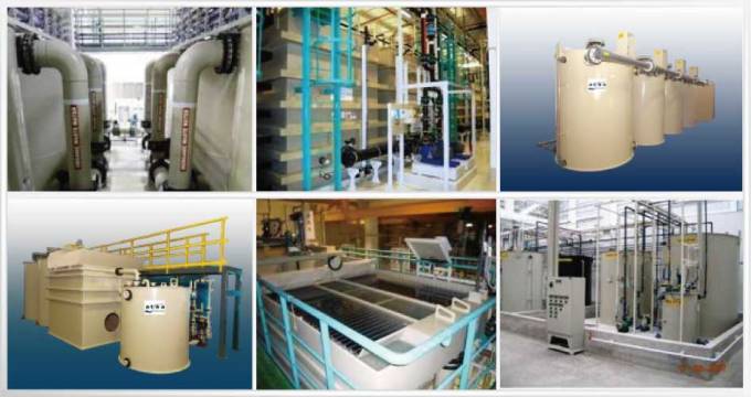
| | موضوع: API UNITES PHOTOS/صور لوحدات فصل الزيوت عن مياه الصرف الأربعاء فبراير 22, 2012 3:48 am | |
| [img]  [/img] [img]  [/img] [img]  [/img] [img]  [/img] [img]  [/img] [img]  [/img] [img]  [/img] | |
|


![[MSF+3.jpg]](https://2img.net/h/4.bp.blogspot.com/_SynCnHGx75g/Shl2T3oVhsI/AAAAAAAAAEY/_7oem5pvQ3I/s1600/MSF%2B3.jpg)