Admin
Admin

عدد المساهمات : 3762
تاريخ التسجيل : 15/09/2009
العمر : 57
الموقع : مصر
 | موضوع: Specification of Water Wells/Lمواصفات مياه الابار والمعايير الاساسية لانشاء ابار صالحة للشرب  السبت مارس 03, 2012 4:18 pm السبت مارس 03, 2012 4:18 pm | |
| Specification of Water Wells
BY
GENERAL.DR
BAHAA BADR
TECHNOLAB EL-BAHAA GROUP
ABSTRACT
The water well, or wells serving a groundwater heat pump
(GWHP) system, are as pivotal a part of the mechanical design
as the boiler and cooling tower would be in a water loop
system.
As such, they should warrant the same degree of attention
with respect to specification as the more conventional
components would receive.
Unfortunately, this is rarely the
case, and the HVAC design engineers’ lack of familiarity with
the topic is sometimes at fault. This paper is intended to identify
the key sections of water well specifications and briefly discuss
their contents.
INTRODUCTION
The design and construction of water wells is a topic unfamiliar
to many, if not most, mechanical engineers.
As a result,
the task is often poorly handled, or worse, ignored. This rarely
results in a well completed in the best interests of the owner.
Although the HVAC engineer may not always be directly
responsible for the design of the well, its specification, or
construction management, they are, in the context of a groundsource
heat pump system, a critical part of the mechanical
design.
Consequently, it is in the interest of the HVAC design
engineer to become familiar with the terminology of water
wells and the key specification issues relating to their
construction.
The goal of this paper is not to provide suggested
specification text but to briefly discuss the key sections found
in a well-specification document and comment on the contents
of each.
WATER WELL TYPES
The design of a water well and the preparation of the
construction documents related to it are functions of several
documents related to it are functions of several
issues, including the purpose of the well (domestic, municipal,
irrigation, injection, etc.),
its capacity (low <10 gpm [0.6 lps]),
medium 10 - 100 gpm [0.6 - 6.0 lps], high >100 gpm [>6.0
lps]),
the geology penetration (consolidated, unconsolidated,
combination), and the construction method (mud rotary, air
rotary, reverse circulation, cable tool) (EPA 1975).
Since this
paper is limited to wells serving commercial GWHP systems
(normally medium to high capacity, rotary constructed), the
primary influence on design and specification is the nature of
the geology penetrated in the process of construction.
Although there are an infinite number of well construction
designs, for a substantial part of the country the alternatives
can be reduced to some variation on one of the two basic
designs .
Special modifications to
these basic designs can be made to accommodate conditions
such as artesian aquifers, injection rather than production, and
corrosive water.
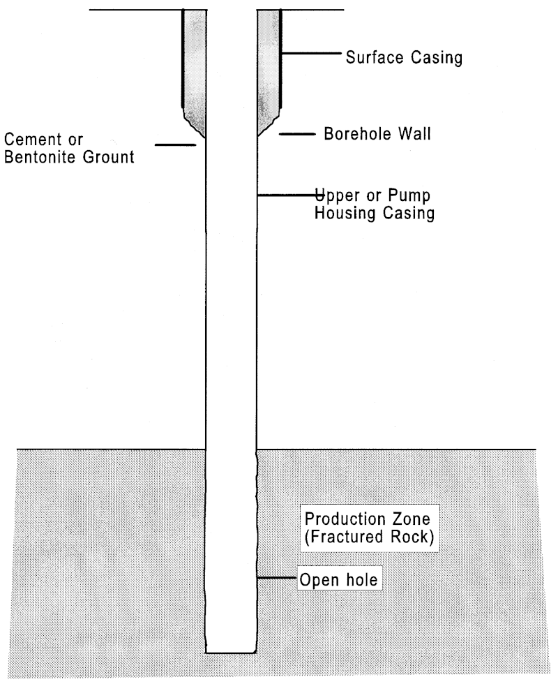
The simplest well is one completed in rock
formations in which the water is produced from fractures in
the rock.
In these wells, sometimes called “open hole completions,”
no casing or screen is necessary to stabilize and filter
the aquifer materials adjacent to the well bore due to the nature
of the geology.
Casing is normally placed in the upper portion
of the well for a short distance to accommodate the installation
of a surface seal.
The second type of well, completed in unconsolidated
materials (sand, gravel, clay, soil, and mixtures thereof), is
more complex.
In these applications the well is completely
lined with casing, screen, and sometimes an artificial filter or
“gravel pack.”
In unconsolidated settings, the variation in the
size of the aquifer materials results in the need to adequately
filter the water entering the well to control the content of sand
in the water produced.
In some cases, a screen alone, attached
to the bottom of the casing, will provide the necessary filtering
of the water.
In other cases, the screen must be accompanied
by an artificial filter or gravel pack located between the screen
and the borehole wall.
This gravel is sometimes only a formation
stabilizer of relatively uncomplicated description.
For
other situations, a more carefully specified filter gravel must
be used.
The need for accurate descriptions of these components
and their installation results in a more voluminous specification
document for these wells than for an open hole well.
WATER WELL TERMINOLOGY
Prior to discussing the details of individual well specification
sections, it is useful to review a few of the key terms
relating to water wells and their operation.
includes
many of these terms. In any well, under nonpumping conditions,
the level at which the water resides in the well is known
as the static water level.
When the pump is started, the water
level will drop to a new level known as the pumping level, and
this level is a function of the pumping rate.
The difference
between the static water level and the pumping level is
referred to as the drawdown.
Dividing the pumping rate by the
drawdown yields a value known as the specific capacity with
units of gpm/ft (lps/m).
This value provides a rough indication
of the aquifer/well capacity to produce water.
The drawdown
is the manifestation of the “cone of depression,” which forms
around the well in response to pumping.
The lower portion of the well in the production zone may
be completed with only a borehole (in rock formations), a
screen, or a screen and an artificial filter (gravel pack),
depending on the nature of the aquifer materials.
Casing is
placed in the well to support the borehole and prevent collapse
to accommodate the installation of a pump or to facilitate the
placement of a seal.
The diameter of the innermost well
casing, known as the pump housing casing, is primarily a function
of the size of the pump to be installed.
Submersible
pumps, the type most often used in GWHP systems, often
require one size smaller casing due to their operation at 3600
rpm than line shaft driven pumps, which normally operate at
1800 rpm or less.
Other well casing is sometimes installed in
the upper portion of the well to accommodate the installation
of the surface seal. The surface seal, often a cement grout,
prevents surface water from draining down between the casing
and borehole into the subsurface.
WELL SPECIFICATION ISSUES
There are several areas that should be addressed in the
course of preparing a specification for a water well, and Table
1 presents the most important of these.
Some issues relate only
to certain types of wells or conditions, but this table is a useful
checklist for the specification process.
There are two
approaches to the design and specification of a water well. If
there are other wells nearby producing from the same formation
and approximately the same yield, the design of a new
well can be based upon the existing wells.
This is an acceptable
practice assuming the existing wells operate without
problems.
In other cases, the well design is determined to a
large extent by the geology and aquifers it penetrates.
A
preliminary design can be developed, but it may be necessary
to modify this in the course of construction.
For a well completed in a consolidated formation (rock),
the sections on screen, gravel, and sometimes development
can be eliminated.
Scope of Work
This is the section in which a general description of the
work is provided.
The scope at a minimum includes the type
of drilling rig to be used, approximate depth, number of wells,
and the expected yield for production wells.
When available,
the scope may also provide additional detail on the general
construction of the well in terms of casing size, depth, screentype
diameter, location, and development method.
If a performance
guarantee with respect to yield, or specific capacity is
required, this is also included in the scope section (RMC
1985).
Nontechnical Well Issues
Nontechnical well issues (a phrase used in this paper and
not in the specification document) include items not directly
related to the technical details of construction.
Contractor
qualifications, site description, noise control, archeological
discovery, and facilities provided by the owner are normally
covered as individual sections but are grouped together here
for simplicity.
The paragraph on contractor qualifications normally
includes a minimum experience requirement (number of wells
similar to the current project, years in business) and a licensing
requirement.
Details for a list of reference projects may also be
spelled out.
The site description is especially important,
particularly if potential drillers are from outside the area.
A
physical description of the site is provided along with background
on the geology/hydrogeology. If available, well
completion reports from nearby wells are a key part of this
information.
Noise is normally addressed through the specification
of acceptable operating hours for drilling operations.
The facility provided by the owner is one of the few specification
issues actually requested by contractors, particularly in
the case of site access and water availability.
Sufficient water
supply for the drilling operation is a critical issue.
Equipment Requirements
In this section, a specification is made with respect to the
drilling rig capabilities required and/or a form is provided on
which the contractor must submit a description of the equipment
to be used in the construction of the well.
In cases of shallow
wells, such issues as mast, hook, and draw-work load
limits are not often approached, even for small rigs. As a
result, it is possible to omit this section in some small projects.
Drilling Fluid
This is a section that relates primarily to conventional
(direct) rotary drilling operations. In this section an accept-
able value, or range of values, for key drilling fluid (sometimes
called “mud”) parameters is provided.
The drilling
fluid, or mud, is circulated down the rotating drill pipe, out
the bit, and back up the annular space between the borehole
wall and the drill pipe.
It serves to lubricate and cool the bit,
carry away the cuttings, and form a “cake,” stabilizing the
borehole walls. Included are such characteristics as weight
(11 lb/gal maximum), marsh funnel viscosity (32-38 seconds
maximum), 30-minute water loss (15 cc maximum), filter
cake formation (2/32 in. [1.6 mm] maximum), and sand
content (2% maximum).
It should be understood that fluid
parameters are regularly adjusted in the course of drilling to
accommodate situations encountered in the construction
process. In some fluid specifications, reference is made to a
requirement for a drilling mud engineer’s involvement in the
project.
On small projects, these services are usually available
to the drilling contractor from the mud vendor, and the
specification of a mud engineer’s availability to the contractor,
rather than his on-site presence, is appropriate.
Drilling Program Submittal
This section provides the requirements for submission by
the contractor of a schedule of tasks to be completed in the
process of completing the well.
Included are personnel, schedule
of tasks (drilling, casing, screen gravel installation, development),
and details of the drilling fluid makeup (additives)
(RMC 1985).
Formation Sampling
Formation sampling is described as a pivotal part of the
well drilling process in this section.
Decisions are made, based
on samples from the production zone of the well, as to the
screen-slot size and gravel-pack gradation necessary for
completion.
If a pilot bore is used in rotary drilled wells, the
samples are taken as the pilot hole progresses.
If the approximate
depth of the production zone is known, it is normal practice
to specify a regular interval over which samples will be
taken; the handling, appropriate containers, and labeling of the
samples; along with the individual (or organization) to whom
they should be delivered.
Sieve analysis of these samples
provides the data upon which screen-slot size and gravel-pack
size distribution are based.
This consists of passing the
samples through a set of progressively finer sieves or screens
to determine the size distribution of the sampled material.
Logs/Records
Depending on the depth, drilling method, and purpose of
the well, a variety of logs and reports may be specified in this
section.
For wells of the type used for GSHP systems, it is
normally sufficient to specify the depth and physical description
of strata penetrated, the depth of water producing intervals,
associated static water levels, and penetration rates
accomplished on the driller report.
If well completion reports
the driller report.
If well completion reports
are required by regulatory agencies, copies should be provided
to the owner/engineer as well.
Reporting requirements for
flow testing, development, and plumbness/alignment are
covered in those respective sections.
Plumbness/Alignment
Plumbness (deviation from the vertical) and alignment
(“straightness”) of the well are issues of importance with
respect to the installation of a pump in the well. In particular,
lineshaft-type pumps are much more sensitive to the alignment
issue than are submersible pumps.
With a rotating shaft
extending from the surface to the pump (sometimes hundreds
of feet down in the well), wells in which line-shaft pumps are
to be installed must be held to tighter tolerances than submersible
installations.
Two approaches can be taken to this specification.
For small projects using a submersible pump, the
required test often involves a 40 ft (12 m) section of pipe, 2
in. (12 mm) smaller in diameter than the inside of the casing,
which must be capable of passing freely through to the bottom
of the pump housing casing.
For larger wells, or those using
line shaft pumps, a more sophisticated test involving a device
for measuring deviation of the bore is necessary.
Casing
Casing is a term that refers to tubular material extending
from the surface to some depth in the well.
It is installed to
accommodate the sealing of the well, to stabilize the walls of
the borehole, or to allow the installation of screen or liner
(tubular products not extending to the surface).
In shallow
wells of the type serving GWHP systems, at least two types of
casing are often found. Surface casing is installed a short
distance (to the first impermeable strata or minimum of 18 ft
[6 m] by many codes) from the surface to a depth sufficient to
allow the installation of the surface seal (usually cement grout)
between the surface casing and the well bore.
The surface
casing also helps to support near-surface unconsolidated
materials during the drilling operation.
Sometimes this surface
casing is removed as the grout is placed.
The second casing type is the pump-housing casing,
which, as the name implies, is the casing in which the pump is
installed.
This casing is installed inside the surface casing,
from the surface to the top of the screen in gravel pack wells
or to the top of the producing interval in shallow open hole
wells.
If used, the screen would be attached to the bottom of
the pump housing casing.
In the casing portion of the specification information, the
size, wall thickness, material, and installation method of the
casing are provided, along with the location (depth) in some
cases.
Surface casing is normally at least 2 inches larger than
the pump housing casing in order to accommodate the placement
of the grout to an adequate thickness.
Diameter of the
pump housing casing is a function of the pump to be paced in
the well. Generally, it is desirable to have a pump housing
casing of two nominal sizes larger than the pump to be
installed.
Pump bowl (impeller housing) diameter is related to
pump type and flow rate. Submersible pumps, which typically
operate at 3600 rpm, produce more flow per unit diameter than
line shaft pumps, which operate at 1800 rpm or less. In most
commercial applications, a minimum of 6 in. (150 mm) casing
would be used with 8 in. (200 mm) for flows >100 gpm (6 lps)
and 10 in. (250 mm) for flows > 300 gpm (18 lps) (Kavanaugh
and Rafferty 1997).
Casing wall thickness is normally specified
in this section. Wall thickness requirements vary with
drilling method, depth, diameter, and seal placement. In
general, for sizes up to 14 in. (350 mm) and depths to 600 ft
(180 m), a 250 in. (6 mm) wall thickness is acceptable
(AWWA 1997).
Most wells serving commercial applications
use carbon steel well casing.
Plastic materials can be used in
a very shallow applications permit. Detailed specifications are
available on the placement of the casing; however, drilling
method (rig type) largely determines the techniques used, and
in many cases, this issue simply adds needless detail to the
well specification.
Screen
The screen plays a critical role in the performance of the
well since it provides the filtering of the water entering the
well. In this section, the type of screen, aperture size, diameter,
length, entrance velocity, and material of the screen are
described, along with the installation method.
The determination
of aperture (slot) size is made based on the results of a
sieve analysis of the drill cutting samples from the production
interval of the well.
On occasion, when sufficient information
is available, the screen can be specified based on the performance
of existing wells in the same aquifer.
For this to be an
effective strategy, detailed knowledge of the geology must be
available. In applications where no gravel pack will be used,
the screen slot size is specified as that which will retain 30%
to 50% of the aquifer materials, depending on the corrosiveness
of the water and the uniformity coefficient of the aquifer
materials.
In applications where a gravel pack will be used, the
slot size is selected for retaining 70% to 100% of the gravel
pack materials (AWWA 1997).
All slot size selections are
based on the aquifer materials sieve analysis distribution
curve.
The specification can allow the contractor to have a lab
do the analysis with the results delivered to the owner/engineer
for approval, or the samples can be delivered directly to
the owner/engineer for analysis.
There are several types of screens available, and two of
the most common are wire-wound and louvered. Wire-wound
screens (continuous slot) provide a higher degree of open area
through which the water can pass (a critical issue in fine sand
aquifers), are generally more expensive than other types, and
with larger diameters are lower in collapse strength.
Louvered
screens are generally less expensive, have higher collapse
strength and lower open area, and provide for more effective
development using swabbing.
Entrance velocity specification
influences the type of screen.
In many references (some written
by a major manufacturer of wire wound screen) an
entrance velocity limit of 0.1 ft/sec (0.03 m/s) is cited. This
low velocity tends to require the use of screens with high open
area ratios (wire wound).
Other research suggests that
entrance velocities of as much as an order of magnitude
greater than this do not significantly reduce well performance
in many applications.
Wire-wound screens are normally
constructed of 304 stainless steel to reduce corrosion problems.
Louvered screens can be of carbon steel in many applications
due to their higher strength.
Placement of the screen, like the placement of the casing,
is best left to the contractor since it is determined to a large
extent by drilling method.
Gravel
Gravel is sometimes placed outside the screen to support
the aquifer materials (called formation stabilizer) or to
increase near bore permeability and to assist in filtering aquifer
materials (called artificial filter).
Regardless of function,
the common term for the practice is gravel pack.
The importance
of the selection of the size distribution of the gravel
material is much greater when it is intended to serve as an artificial
filter.
Issues to be addressed are size, gradation (uniformity
coefficient), geology, thickness, and placement.
As in the case of the screen slot size selection, the determination
of the gravel pack parameters is based on the cuttings
sieve analysis results.
One common criterion for the gravel
pack specifies that it have a 70% retained grain size of 4 to 6
times the 70% grain size of the cuttings sample and a uniformity
coefficient (40% size divided by 90% size) of not greater
than 2.5 (EPA 1975). Gravel material should be clean and well
rounded with a maximum of 10% flat surfaces and should be
a minimum of 95% siliceous in content (to avoid dissolution
in low pH water).
The thickness of the gravel pack should be between 3 in.
and 8 in. (75 mm and 200 mm) thickness. Placement of the
gravel is generally accomplished by either pouring from the
surface (in shallow wells) or by placement through a tremie (in
wells of greater than 1000 ft [300 m] depth) (RMC 1985). In
most shallow wells of the type serving GWHP systems, the
pack material will be poured from the surface.
This is done
while circulating drilling fluid down the drill pipe and up the
annular space (between the casing and the bore wall). A key
part of the specification is the requirement to maintain drill
fluid density below a specific density limit (9.1 lb/gal). The
fluid tends to pick up drilling mud from the walls of the borehole
as the gravel is placed. The viscosity limit requires this
material to be continuously removed during the process.
The
gravel placement should be completed in one continuous operation.
Development
The process of development is one in which the fines in
the aquifer material or gravel pack, and any remaining drilling
fluids in the near bore area, are removed by a variety of methods.
The development process is divided into two phases —
initial development using the drilling rig, and final development
by pumping after the rig has been removed.
To some
extent the type of development is influenced by the geology
and well type.
Specifications describe the type of development,
when it should be terminated, and, most importantly, the
acceptable sand production for the well in the final development.
In gravel pack wells, preliminary development is often
accomplished by the so-called “flushing” method, using a tool
known as a “double swab” that can be accomplished with the
rotary rig. A more effective method, known as line swabbing,
requires the use of a cable tool rig.
Both of these methods are
best applied with louver-type screens. Jetting is a development
technique often used most effectively with wire wound
screens, and it involves directing high-velocity water jets at
the screen/gravel pack.
Air-lift pumping and sand pumping
(used in naturally developed wells) are other methods of
development.
Preliminary development is carried on until all of the
fines and sediment have been removed from the gravel pack
and the pack ceases to settle.
Final development is carried on
until the specified sand content of the production water is
reached. This limit is typically expressed as a sand content in
ppm after some period of pumping.
Water samples for chemical
analysis can be taken toward the end of the preliminary
development or during final development pumping.
Water Samples
Water samples for the purpose of analysis for system
design (corrosion and scaling) should be taken during the
development pumping.
The specification describes the size of
the sample, the type of container in which it will be stored
(normally a container supplied by the lab doing the analysis),
and when the sample should be taken (after 1 hour of pump
operation).
Finally, the chemical constituents to be tested are
listed.
All major anions and cations, along with alkalinity,
total hardness, carbon dioxide, hydrogen sulphide, and
oxygen should be included.
Flow Testing
Flow testing of the well provides important data for the
design of the heat pump system since the groundwater flow
rate chosen is based on pumping power (flow and drawdown).
There are several types of flow tests that can be done on
a production well.
In many cases, a step drawdown test is done
for wells serving GWHP systems. In this test, the well is
pumped at three rates until water level has stabilized.
The
well. In many cases, a step drawdown test is done
for wells serving GWHP systems. In this test, the well is
pumped at three rates until water level has stabilized.
The
specification describes the flow rates, instrumentation (for
water level and flow data), frequency of readings, length of
test, and facilities for disposal of the water.
This so-called
single well test provides information primarily on the well
itself (yield, drawdown, specific capacity).
A more sophisticated
test in which nearby wells are monitored provides information
on the aquifer. These tests are rarely done for GWHP
systems.
Generally, the flows chosen approximate one-third, twothirds,
and full design flow anticipated for the system served.
Starting with the lowest flow, the pump is operated at a
constant rate until the water level in the well has stabilized, at
which time the flow is increased to the next rate.
Water level
is typically measured with an electric continuity device on the
end of a calibrated spool of wire.
Flow is measured with an
orifice plate discharging to atmosphere and pressure across the
plate monitored with a manometer.
Flow tests are often
subcontracted to a well pump contracting firm.
Some jurisdictions require that any well penetrating a
potential drinking water aquifer be sterilized.
The paragraph
relating to sterilization describes methods, chemical concentration,
and length of the sterilization procedure, which
normally consists of chlorine treatment.
Abandonment
In the event that the well is unsuccessful and cannot be
used for the intended purpose, it must be abandoned according
to the requirements of the regulatory agency responsible for
water wells.
Most states have very specific regulations covering
abandonment, which typically require filling the well with
an impermeable material—often cement grout.
It is not necessary
to cover these procedures in detail.
Referencing the
appropriate state administrative rule will suffice.
INJECTION WELL ISSUES
Injection wells, used for disposal of the water after passing
through the heat pump system, differ from production
wells in several ways.
Two of the more important are screen
design and seal placement.
Most references recommend a
water velocity through the screen of one-half of that used in the
production well.
It appears that this guideline is primarily
related to the allowance for plugging of the injection screen
with particulate carried into the well with the water.
From this
comes the widely held perception that the injection well
should have a larger diameter than the production well.
This
is not the case.
The reduced screen velocity can be achieved by
screening more of the aquifer since production wells in water
table aquifers normally screen only the lower one-half to onethird
of the aquifer.
Beyond this, the need for the additional
screen area assumes the presence of particulate in the injected
fluid. If the production well is sand free, or if a surface strainer
is used to minimize sand, the additional screen may not be
necessary.
Sealing of an injection well should be done in much the
same way as a production well penetrating an artesian aquifer.
The reason for this is that in the course of the operation of the
well, the pressure exerted on it is greater than the natural pressure
of the aquifer it penetrates.
As a result, there is a tendency
for water to migrate up around the casing toward the surface.
If the well is exposed to a positive pressure at the ground
surface, the potential exists for water to leak out around the
casing at the surface.
To prevent this, injection wells should be
sealed from just above the injection zone, continuously to the
surface, with a minimum 2 in. (50 mm) annular (between the
casing and the well bore wall) cement seal.
The injection stream should be introduced into the well
using an injection tube terminating below the water surface.
This prevents the injected water from cascading down from
the well head and generating air bubbles in the process.
Bubbles driven out into the aquifer can act as an obstruction to
water flow in much the same fashion as particulate matter.
SPECIFICATION TEXT
The goal of this paper has been to identify the key sections
necessary in a specification document for a water well and to
comment on the general contents.
Actual guide specification
text has been published by many others (RMC 1985; AWWA
1997; EPA 1975; MWWDA 1970).
In many cases these references
are published in the form of guidelines for the specification
of water wells in which explanatory paragraphs are
included ahead of actual specification sections.
Editing is
normally required to use these sources in construction documents.
| |
|


![[MSF+3.jpg]](https://2img.net/h/4.bp.blogspot.com/_SynCnHGx75g/Shl2T3oVhsI/AAAAAAAAAEY/_7oem5pvQ3I/s1600/MSF%2B3.jpg)