مجموعة تكنولاب البهاء جروب
تحاليل وتنقية ومعالجة المياه
|
تنظيف وتطهير وغسيل واعادة تاهيل الخزانات

معمل تكنولاب البهاء جروب
للتحاليل الكيميائية والطبية
والتشخيص بالنظائر المشعة
للمخدرات والهرمونات والسموم
وتحاليل المياه

مجموعة
تكنولاب البهاء جروب
لتصميم محطات الصرف الصناعى والصحى
لمعالجة مياه الصرف الصناعى والصحى
مجموعة تكنولاب البهاء جروب
المكتب الاستشارى العلمى
دراسات علمية كيميائية
معالجة الغلايات وانظمة البخار المكثف
معالجة ابراج التبريد المفتوحة
معالجة الشيللرات
مجموعة تكنولاب البهاء جروب
اسنشاريين
كيميائيين/طبيين/بكترولوجيين
عقيد دكتور
بهاء بدر الدين محمود
رئيس مجلس الادارة
استشاريون متخصصون فى مجال تحاليل وتنقية ومعالجة المياه
متخصصون فى تصنيع وتصميم كيماويات
معالجة الصرف الصناعى والصحى
حسب كل مشكلة كل على حدة تصنيع وتحضير كيماويات معالجة المياه الصناعية
مؤتمرات/اجتماعات/محاضرات/فريق عمل متميز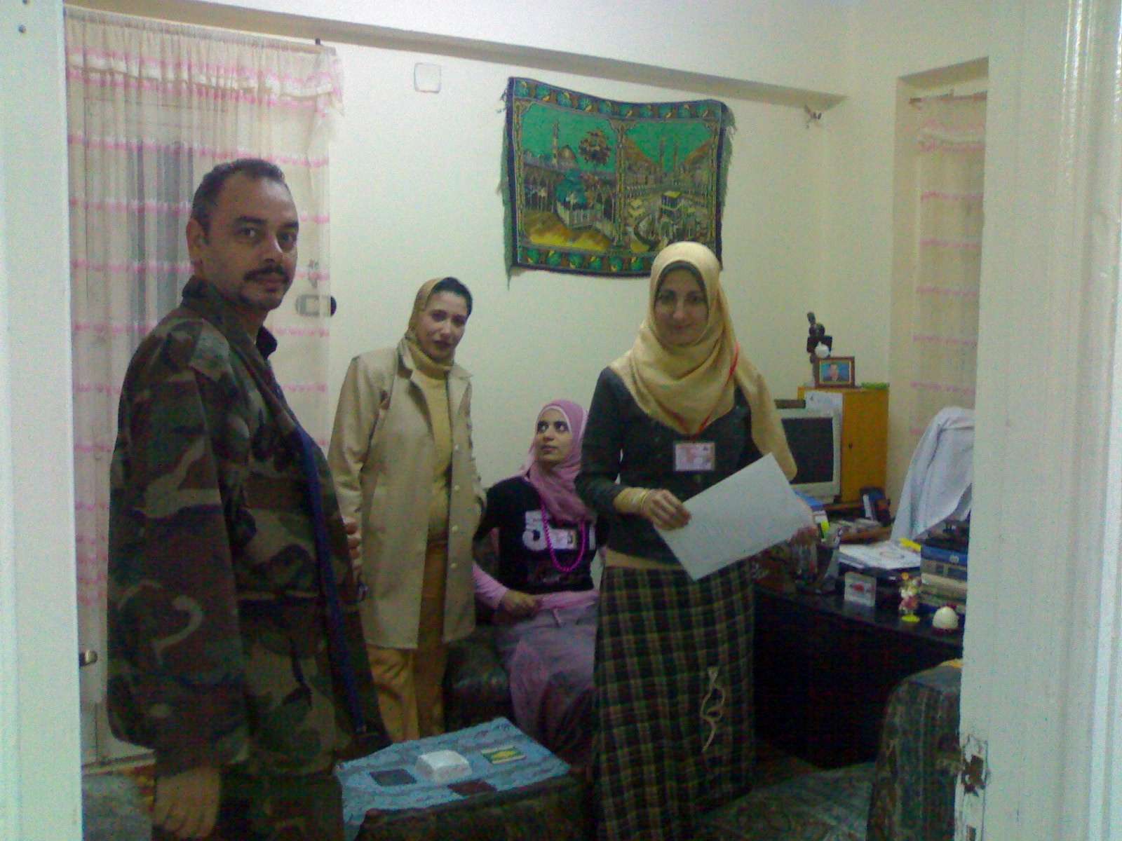 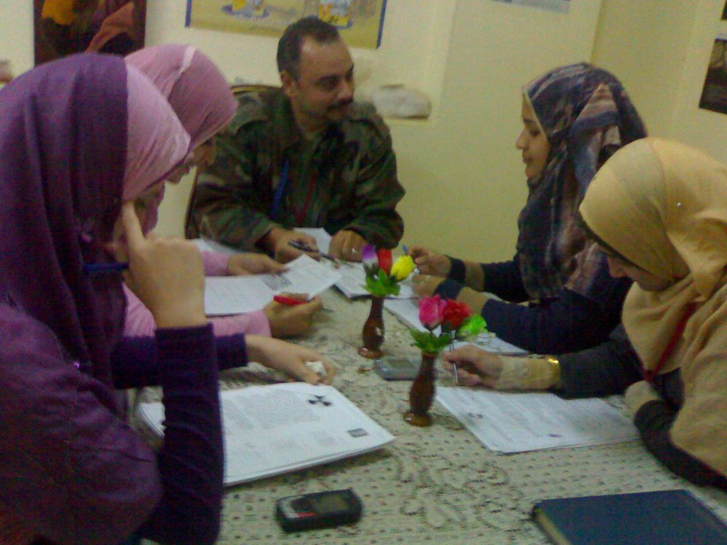 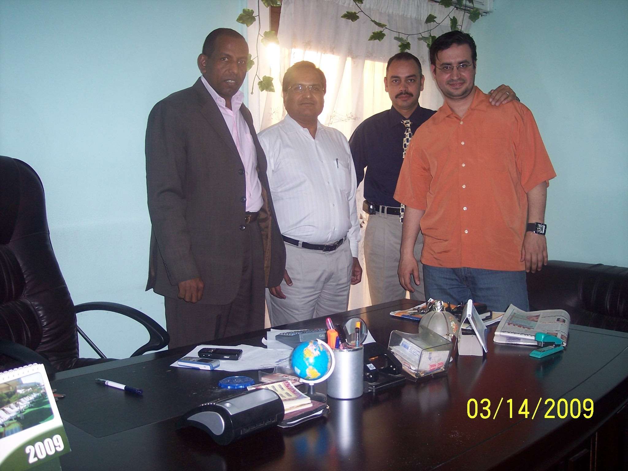   صور من وحدات معالجة المياه
 technolab el-bahaa group technolab el-bahaa groupTECHNOLAB EL-BAHAA GROUP
EGYPT
FOR
WATER
TREATMENT/PURIFICATION/ANALYSIS
CONSULTANTS
CHEMIST/PHYSICS/MICROBIOLIGIST
INDUSTRIAL WATER
WASTE WATER
DRINKING WATER
TANKS CLEANING
CHAIRMAN
COLONEL.DR
BAHAA BADR EL-DIN
0117156569
0129834104
0163793775
0174041455 تصميم وانشاء محطات صرف صناعى/waste water treatment plant design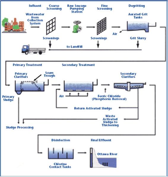 technolab el-bahaa group egypt We are a consultants in water treatment with our chemicals as:- Boiler water treatment chemicals Condensated steam treatment chemicals Oxygen scavenger treatment chemicals Ph-adjustment treatment chemicals Antiscale treatment chemicals Anticorrosion treatment chemicals Open cooling tower treatment chemicals Chillers treatment chemicals Waste water treatment chemicals Drinking water purification chemicals Swimming pool treatment chemicals Fuel oil improver(mazote/solar/benzene) technolab el-bahaa group
egypt
We are consultants in extraction ,analysis and trading the raw materials of mines as:-
Rock phosphate
32%-30%-28%-25%
Kaolin
Quartez-silica
Talcum
Feldspae(potash-sodumic)
Silica sand
Silica fume
Iron oxid ore
Manganese oxid
Cement(42.5%-32.5%)
Ferro manganese
Ferro manganese high carbon technolab el-bahaa group
web sites
e-mails
water treatment unit design 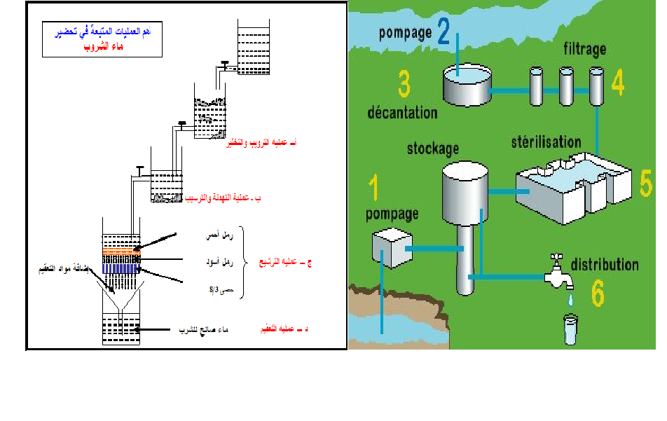
وكلاء لشركات تركية وصينية لتوريد وتركيب وصيانة الغلايات وملحقاتها
solo agent for turkish and chinese companies for boiler production/manufacture/maintance
وكلاء لشركات تركية وصينية واوروبية لتصنيع وتركيب وصيانة ابراج التبريد المفتوحة 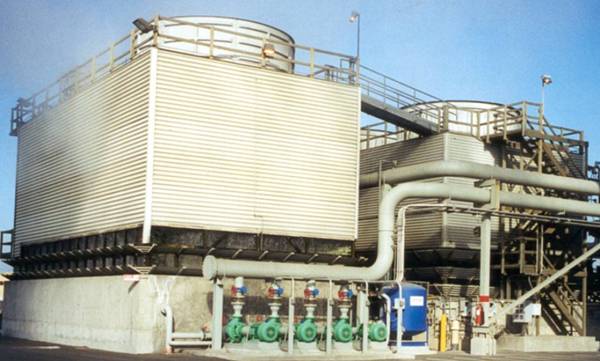
تصميم وتوريد وتركيب الشيللرات
design/production/maintance
chillers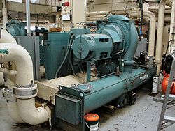 ابراج التبريد المفتوحة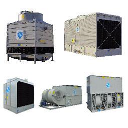 مجموعة تكنولاب البهاء جروب
المكتب الاستشارى العلمى
قطاع توريد خطوط انتاج المصانع
نحن طريقك لاختيار افضل خطوط الانتاج لمصنعكم
سابقة خبرتنا فى اختيار خطوط الانتاج لعملاؤنا
1)خطوط انتاج العصائر الطبيعية والمحفوظة والمربات
2)خطوط انتاج الزيوت الطبيعية والمحفوظة
3)خطوط انتاج اللبن الطبيعى والمحفوظ والمبستر والمجفف والبودرة
4)خطوط تعليب وتغليف الفاكهة والخضروات
5)خطوط انتاج المواسير البلاستيك والبى فى سى والبولى ايثيلين
6)خطوط انتاج التراى كالسيوم فوسفات والحبر الاسود
7)خطوط انتاج الاسفلت بانواعه
 محطات معالجة الصرف الصناعى والصحى بالطرق البيولوجية والكيميائية محطات معالجة الصرف الصناعى والصحى بالطرق البيولوجية والكيميائية9)محطات معالجة وتنقية مياه الشرب
10)محطات ازالة ملوحة البحار لاستخدامها فى الشرب والرى
11)الغلايات وخطوط انتاج البخار الساخن المكثف
12)الشيللرات وابراج التبريد المفتوحة وخطوط انتاج البخار البارد المكثف
للاستعلام
مجموعة تكنولاب البهاء جروب
0117156569
0129834104
0163793775
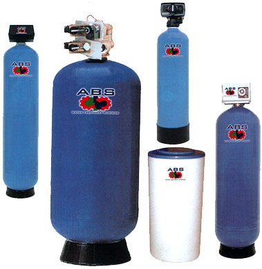
القاهرة-شارع صلاح سالم-عمارات العبور-عمارة 17 ب فلا تر رملية/كربونية/زلطيه/حديدية
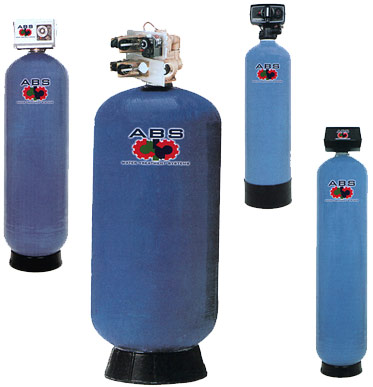
وحدات سوفتنر لازالة عسر المياه
مواصفات مياه الشرب
Drinking water
acceptable
values
50 | colour | acceptable | Taste | nil | Odour | 6.5-9.2 | ph |
1 mg/dl | pb | 5 mg/dl | as | 50 mg/dl | cn | 10 mg/dl | cd | 0-100mg/dl | hg | 8 mg/dl | f | 45 mg/dl | N02 | 1 mg/dl | Fe | 5 mg/dl | Mn | 5.1 mg/dl | Cu | 200 mg/dl | Ca | 150 mg/dl | Mg | 600 mg/dl | Cl | 400 mg/dl | S04 | 200 mg/dl | Phenol | 15 mg/dl | zn |
الحدود المسموح به
ا لملوثات الصرف الصناعى
بعد المعالجة
Acceptable
values
treated wate water
|
7-9.5 | ph | 25-37 c | Temp | 40 mg/dl | Suspended solid | 35 mg/dl | bod | 3 mg/dl | Oil & grase | 0.1 mg/dl | hg | 0.02 mg/dl | cd | 0.1 mg/dl | cn | 0.5mg/dl | phenol | 1.5 ds/m | conductivity | 200 mg/dl | na | 120 mg/dl | ca | 56 mg/dl | mg | 30 mg/dl | k | 200 mg/dl | cl | 150 mg/dl | S02 | 0.75 mg/dl | Fe | 0.2 mg/dl | Zn | 0.5 mg/dl | Cu | 0.03 mg/dl | Ni | 0.09 mg/dl | Cr | 0.53 mg/dl | لb | 0.15 mg/dl | pb |
محطات تحلية مياه البحر بطريقة التقطير الومضى على مراحل MSF+3.jpg (image)محطات التقطير الومضى لتحلية مياه البحر2![[MSF+3.jpg]](https://2img.net/h/4.bp.blogspot.com/_SynCnHGx75g/Shl2T3oVhsI/AAAAAAAAAEY/_7oem5pvQ3I/s1600/MSF%2B3.jpg) some of types of tanks we services
انواع الخزانات التى يتم تنظيفها
ASME Specification Tanks
Fuel Tanks
Storage Tanks
Custom Tanks
Plastic Tanks
Tank Cleaning Equipment
Double Wall Tanks
Septic Tanks
Water Storage Tanks
Fiberglass Reinforced Plastic Tanks
Stainless Steel Tanks
Custom / Septic
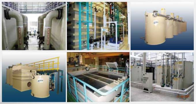
مراحل المعالجة الاولية والثانوية والمتقدمة للصرف الصناعى

صور مختلفة
من وحدات وخزانات معالجة الصرف الصناعى
التى تم تصميمها وتركيبها من قبل المجموعة
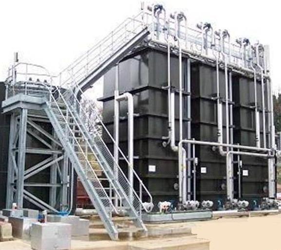
صور
من خزانات الترسيب الكيميائى والفيزيائى
لوحدات معالجة الصرف الصناعى
المصممة من قبل المحموعة
 technolab el-bahaa group
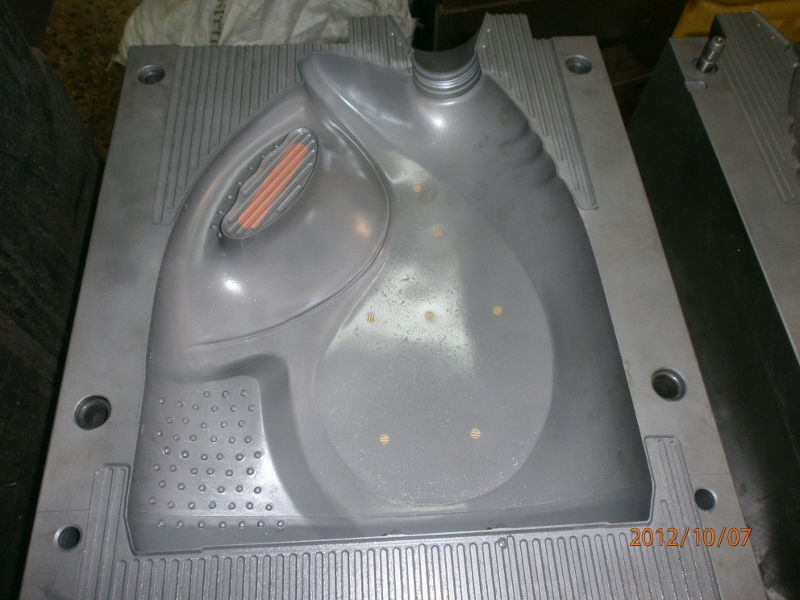
 technolab el-bahaa group technolab el-bahaa group technolab el-bahaa group technolab el-bahaa group technolab el-bahaa group technolab el-bahaa group technolab el-bahaa group technolab el-bahaa group technolab el-bahaa group technolab el-bahaa group technolab el-bahaa group technolab el-bahaa group technolab el-bahaa group technolab el-bahaa group technolab el-bahaa group technolab el-bahaa group technolab el-bahaa group technolab el-bahaa groupمياه رادياتير اخضر اللون
بريستول تو ايه
انتاج شركة بريستول تو ايه - دمياط الجديدة
مجموعة تكنولاب البهاء جروب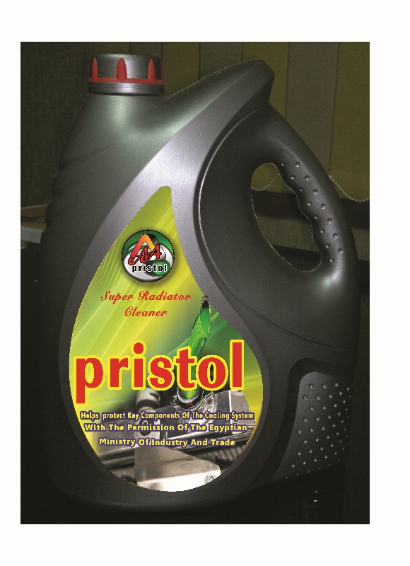
اسطمبات عبوات منتجات شركة بريستول تو ايه-دمياط الجديدة مياه رادياتير خضراء فوسفورية من انتاج شركة بريستول تو ايه بترخيص من مجموعة تكنولاب البهاء جروب 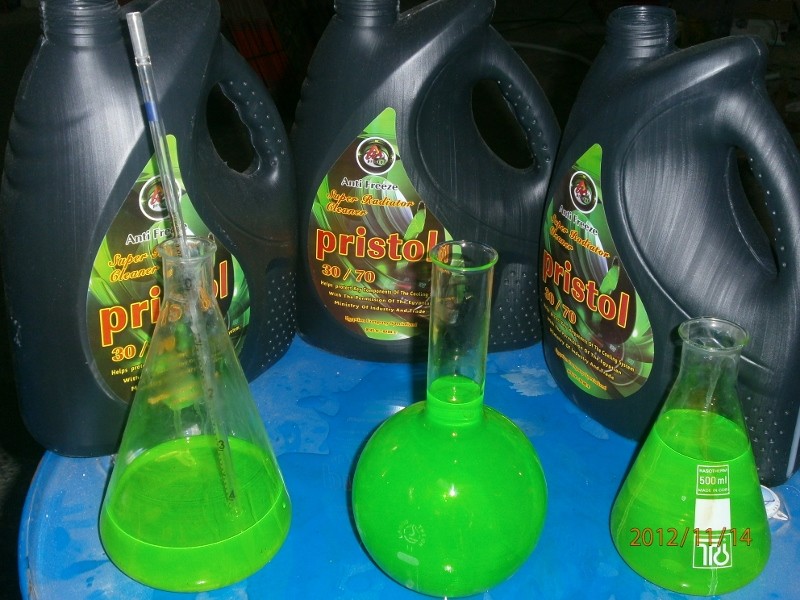

زيت فرامل وباكم DOT3 
|
|
| | مبادئ تصميم وحدة التهوية الطويلة للمعالجة البيولوجية/Extended Aeration |  |
| | | كاتب الموضوع | رسالة |
|---|
Admin
Admin

عدد المساهمات : 3762
تاريخ التسجيل : 15/09/2009
العمر : 57
الموقع : مصر
| موضوع: مبادئ تصميم وحدة التهوية الطويلة للمعالجة البيولوجية/Extended Aeration  الجمعة مارس 23, 2012 10:53 am الجمعة مارس 23, 2012 10:53 am | |
| Extended Aeration
technolab el-bahaa group
general.dr
bahaa badr
Extended aeration is one form of the various forms of suspended growth or “activated sludge” type treatment.
The process is so named because the wastewater is held under aeration for an extended period of time.
The extended aeration process is characterized by having long hydraulic detention times and very long mixed liquor (MLSS) detention times ( longer sludge age than necessary to meet effluent criteria).
The process is designed to operate in the “endogenous” phase of the microbial growth-death curve.
The extended aeration treatment process may be found in a number of different physical configurations that may include smaller (hydraulically) mechanical “package” treatment systems, “race track” or oxidation ditch systems for treatment of municipal wastewater, sequencing batch reactors (SBR), and large industrial treatment systems.
Generally, when the extended aeration process is used for wastewater treatment, the treatment objective is to produce low residual BOD in the treated effluent, minimize the amount of sludge solids which must ultimately be disposed, and/or provide a more stable process that is easier to perform.
The objective of the extended aeration process in this case is to minimize costs. This is accomplished by retaining the solids in the treatment system as long as possible to allow the organic solids to oxidize in the aeration step.
The BOD to MLSS ratio, typically referred to as the F/M ratio, is on the order of 0.1 or less. This means that the influent BOD to the treatment process is barely able to keep the existing microbes alive, and therefore a portion of the microbes die.
For this application, the hydraulic detention time of the aeration chamber should be no less than 24 hours under peak hour flow conditions, with a design maximum monthly flow detention time of no less than 48 hours.
Application for Municipal and Industrial Treatment Systems
For small to moderate sized municipal treatment systems, the oxidation ditch or “race track” treatment process has been commonly applied to the treatment of wastewater.
Depending upon the specific design and operation conditions, this type of system should be classified as an extended aeration system. The objectives in this application are generally somewhat more complex and include the following:
•
Minimize operator attention and effort.
•
Minimize waste sludge sent to the ultimate disposal process.
•
Maximize the probability that effluent standards will be met.
To meet these combined objectives, the hydraulic detention time may not be as long as indicated above. Sludge age may be in the range of 30 days or longer, provided that such a long sludge age does not cause additional operating problems (foaming, bulking, high effluent TSS, etc.).
Industrial applications of the extended aeration process generally have the same objectives as municipal treatment systems. Such treatment plants tend to have serious operational problems such as frequent bulking, foaming, etc., even when safeguards are designed and built into the system.
Design Considerations
General Design Considerations
As indicated above, the extended aeration system is characterized by a long hydraulic detention time, typically 24 hours or longer, and a long solids retention time.
The F/M is around 0.1 or less. This parameter is inversely related to the sludge retention time. See also textbooks or WEF manuals of practice on the subject for the quantitative relationship between F/M ratio and sludge age (sludge retention time).
A significant operational problem associated with extended aeration is that of sludge “bulking” or high-suspended solids in the effluent. The designer should include a selector system before the aeration basin, for suppression of microbes that cause a “bulking” condition in the secondary clarifiers.
Depending upon wastewater characteristics, some form of chemical addition could be included in the sludge return system. Depending upon specific site conditions and which chemicals are readily available, chlorine, hydrogen peroxide, or a similar oxidant may be used to suppress “bulking” organisms, but this approach results in lower effluent quality.
2.
Consideration of Oxygen Transfer
Sizing the oxygen transfer system involves multiple considerations. Oxygen must be supplied to satisfy the change in BOD between the influent and effluent from the aeration basin.
This portion of the oxygen demand is standard for all biological treatment processes. In addition to this demand, oxygen for the demand created by the oxidation of biological solids will also need to be supplied to the system. Finally, due to the long detention times, some nitrification of the wastewater is likely to occur and requires evaluation to determine oxygen requirements.
The reader is again referred to textbooks and the WEF manuals of practice for the methods of sizing oxygen transfer devices. Also, determining oxygen requirements for BOD and nitrogen are described in the same references. Determining oxygen requirements for biological solids is not well described. The following guidelines are recommended for determining oxygen requirements for an extended aeration system:
•
Determine total BOD to be oxidized.
•
Assume that the yield for conversion of BOD to solids is at least 0.5.
•
Biological solids will typically have a 12- to 25-percent inert fraction.
•
Of the remaining 75 to 88 percent, about 20 percent will be refractory and impose a very slow oxygen demand rate.
•
The remaining solids, on the order of 60 to 70 percent, will impose an oxygen demand at the same rate as the BOD and at a ratio of one pound of decomposed solids per one pound of oxygen demand.
For this type of system, special consideration of the selected alpha should be made. Due to higher solids in the wastewater, the “fouled alpha” is somewhat lowered. Values as low as 0.25 have been observed at municipal plants, which include an industrial contribution to the wastewater.
Sizing the oxygen transfer system for an extended aeration system will probably require significant additional aeration capacity compared to other types of biological treatment process.
The degree of conservatism in the application of the above guideline will be a function of the sludge age and the influent BOD concentration. The lower the sludge age and more dilute the influent BOD, the more conservative the above calculation result will be.
Consideration of Secondary Clarification
Extended aeration will likely produce an effluent with a higher suspended solids concentration compared to other suspended growth (activated sludge) type processes.
Loading rates for secondary clarifiers applied to an extended aeration plant should be on the lower end of the recommend range for both hydraulic loading rates and solids loading rates. If SVI is controlled, higher loading rates are possible.
Sludge “bulking” and high solids loss in the secondary effluent can be problematic with an extended aeration plant. Once the treatment plant is operational, the plant operator should consider continuous measurement of the activated sludge VSS and TSS in the mixed liquor.
The VSS/TSS ratio should be observed on a frequent basis, as this parameter may provide a clue to an impending or virtual upset condition. Provided the plant has been designed with methods for adding chemicals to “kill off” the “bulking” organisms, the operator can take corrective action prior to an actual noncompliance condition.
Biological Nutrient Removal
Biological nutrient removal processes remove nutrients from the wastewater effluent using biological systems. Sub-sections below provide a brief description of the nutrient removal objective and the various processes available. For more extensive information and guidelines on nutrient removal technologies
,
Objective
Nutrients (including nitrogen and phosphorous) are removed from the wastewater effluent because these nutrients tend to stimulate weed growth and algal blooms in the receiving water body.
Processes Available
Activated Sludge Plants
Activated sludge plants may be modified or built to provide NDN (nitrification denitrification) in the aeration basins by adding selector and anoxic zones in the plant as the primary effluent.
Return from the end of the aeration basin is sent back to the front of the aeration basin to enter and mix in the front of the basin in an anaerobic zone. It then flows into an anoxic zone.
The anoxic zone is then followed by an aerobic zone. The sizing of the zones is dependent on the flows and solids entering the basins and the return flows from the aeration basin recycle pump.
Depending upon the designer’s intent, the ammonia in the incoming waste stream will be converted to nitrate, nitrite, and/or nitrogen gas, depending on the size of the zones, the recycle rate in the aeration basin, and the alkalinity available in the wastewater.
The above process will also reduce phosphorous.
Oxidation Ditches
Oxidation ditches will remove nitrogen from the waste stream by putting the wastewater through anoxic and aerobic phases as the wastewater is circulated through the oxidation ditch.
Trickling Filters
Trickling filters remove ammonia by recirculating the wastewater through the trickling filter. A modification can be made to the trickling filter plant by adding a solids contactor basin (small aeration tank) that utilizes the aerobic section of the tank to remove ammonia and BOD to reduce the loading on the trickling filter.
Rotating Biological Contactors (RBC
As with trickling filters, achieving ammonia and/or a higher level of nitrogen removal requires an increase in recirculation of the effluent from the RBCs. If the plant is in the design phase, this can generally be accommodated; but in existing plants, the plant’s rated hydraulic capacity will be impacted because of the increased recirculation requirements to meet the nitrogen removal need. Other processes might be considered.
Lagoons
Lagoons reduce the nitrogen in the incoming wastewater. This is done through the long detention time normally found in lagoons. Lagoons can be retrofitted with baffles, pumps, and aeration systems to replicate the activated sludge plants with selectors as noted above.
A/O Process
In activated sludge plants, the process is designed into the aeration basin to provide an anaerobic zone and an aerobic zone (A/O process). This process removes both phosphorous and nitrogen. Existing plants can be retrofitted with an A/O process
Phostrip Process
This is an offline separate process that removes sludge from the final clarifiers and pumps it to a separate process train.
From there, elutriant and anaerobic stripper is combined in a tank, with the water fraction being subjected to lime.
Then the sludge is removed in a separate clarifier where the phosphorous is removed, with the overflow returning to the front of the aeration tank.
The sludge from the elutriant/anaerobic stripper tank is recycled to the front of the aeration tank.
Construction Considerations
Objective
This section identifies some construction considerations related to secondary treatment.
Problems related to items mentioned below can become a source of trouble for wastewater treatment plant operation and maintenance. Construction deficiencies are at the root of many common operational problems, which with appropriate attention can be avoided.
The engineer is generally encouraged to recognize the integral link between design, construction, and operation and provide a prudent level of control to safeguard against these and other common problems.
Possible measures include specific mention in the plans and specifications, submittal requirements, general oversight during construction, special inspection, and inclusion as specific topics for construction meetings.
By being aware of common problem areas, the engineer can apply the appropriate level of precaution to help ensure operational characteristics consistent with the design intent.
Settling and Uplift
This section discusses some considerations associated with the construction, initial filling, and dewatering of large process tanks. These considerations include settling and uplift, which are a concern during both initial construction and subsequent plant expansion or maintenance.
Even with aggressive measures taken to reduce settling, such as dynamic compaction and preloading, some settling at the time of initial tank filling may occur as a result of immense loads associated with large tanks. Loads resulting from initial tank filling will be particularly large when tanks are constructed in banks or connected through a mat foundation.
In this case settling can be sufficient to cause cracking in architectural features such as masonry. In those cases, particularly when it is unlikely that once placed into service all tanks will be simultaneously empty again, it may be appropriate to postpone application of architectural features until after the initial tanks fill in order to avoid this type of cracking.
Settling is a familiar concern and most obvious during initial tank filling. However, settling can also occur to existing facilities as a result of construction dewatering. The reduced hydraulic static pressure may affect neighboring process facilities causing them to settle. The effect on existing structures of dewatering for new construction must be carefully considered.
Any settling, either immediate or long term, will place stress on rigid connections to the structure. To reduce stress as a result of settling on piping at connections, two flexible joints, connected by a short spool piece, should be located just outside the wall face. The flexible joints provide points of rotation and allow the spool piece to provide for vertical displacement.
Uplift is an equally important concern for buried tanks and other subterranean structures. Uplift occurs when the buoyant forces caused by hydraulic static pressure are greater than the downward gravitational forces.
This is a concern whenever a buried structure is at, or below, ground water elevation, particularly if a normally full tank is empty. Schemes to mitigate uplift include locating pressure relief valves in the tank floor to relieve excess hydraulic pressure and placing subterranean wings on the structure to balance uplift forces with the weight of backfill soil.
The pressure relief valves are designed to relieve upward buoyant forces by letting water pass through the floor and into the tank. If this system is used the valves should be immediately and closely inspected to ensure they are properly installed and operational.
If the wing system is used the structure is at risk until backfill is placed. Consequently, any change in ground water elevation, such as the halting of construction dewatering, may affect the structure.
Factors that can quickly affect ground water elevation include heavy rain, mechanical or electrical failure of the dewatering system, and environmental factors that overwhelm the capacity of the dewatering system installed.
Uplift is a concern any time a buried tank is emptied. The potential for uplift is greater with deeper structures and in areas of high ground water.
Secondary Clarifier Slab
Since the primary function of a secondary clarifier is to provide separation of solids from the effluent, an effective solids-removal process is essential. Typically, solids are allowed to settle and then are removed from the clarifier floor with a sweeping collector.
To ensure effective solids removal, it is important that the collector maintain a minimum separation or even contact with the floor slab. This helps ensure that solids are consistently removed from the tank.
It is important that the secondary clarifier slab be finished straight, without depressions or high spots. Warps in the floor slab can impair the solids removal process by creating pockets where the settled solids are not removed. These solids are retained in the tank until they denitrify.
Contrary to the desired removal process, denitrification causes the solids to become buoyant and float. These solids come to the surface and carry over the weirs, degrading effluent quality.
Since a true surface is essential for consistent solids removal, often topping grout will be used as the final surface to improve ability to meet close tolerances. The topping grout surface can be better controlled than the initial slab pour.
If no topping grout pour is called for and the structural slab is to remain the collector contact surface, it is essential that the slab itself be finished true, free of depressions or high spots.
Aeration Piping
Piping used to convey compressed gas to aeration tanks may be either buried or exposed, and can be located outside, in a gallery, or in a pipe chase.
The cost effectiveness and hidden nature of buried piping can be attractive; however, the reduced accessibility of such a configuration may become problematic for aeration piping. With time, aeration piping can develop leaks as a result of either settling, construction defects, or deterioration.
Buried piping is particularly subject to these problems and the reduced accessibility makes repair more difficult. Air expelled from the piping will exfiltrate through cover soil and cracks in paving to the surface, becoming a nuisance.
Consequently, it is recommended that aeration piping receive special attention during construction, especially if buried.
The engineer should encourage or provide aggressive construction inspection in conjunction with leak testing to help ensure proper installation, soil compaction, and joint integrity, and to avoid future air leakage and exfiltration problems. Piping located in a gallery or exposed is somewhat easier to repair and may not need the same level of attention during construction recommended for buried piping.
Control Strategy
This section discusses problems with a common secondary-treatment process control strategy. This strategy relies on flow metering downstream of the primary tanks to control secondary process variables.
The strategy uses primary effluent flow to flow pace secondary process variables. Typically, the flow signal is sent to a programmable logic controller (PLC) or other controller, which processes the flow information and returns a control signal to secondary process elements.
Since the secondary process is relatively sensitive, accurate flow information is required to maintain proper process parameters. However, relying on a flow meter for accurate information can be problematic.
Flow meters inherently have limited accuracy, which can further be reduced by poor field hydraulics, improper installation, poor calibration, flows at the extreme ends of the meter’s accuracy, flows outside the range of calibration, etc.
Problems with flow meter accuracy are compounded during startup and initial operation when flows are much less than design flows. Inaccurate readings cause operation of the secondary system to be problematic.
It is essential that a flow meter not only be selected that can accurately measure the range of flows anticipated, but also that it be properly installed, tested, and calibrated.
Initial calibration should strive for accuracy over the lower range of flows initially experienced, rather than the entire design range anticipated. Understanding the sensitivity of this control strategy on the secondary process and providing the appropriate care will help to ensure a more accurate and less problematic secondary control system.
Operational Considerations
Objective
The objective of this section is to discuss practical process design issues that are vital to the proper performance of the facility.
Plant Hydraulics
Flow Splitting
Flow splitting refers to dividing a flow stream into two or more smaller streams of a predetermined proportional size. Flow splitting allows unit processes such as aeration basins or secondary clarifiers to be used in parallel fashion.
The flow is typically divided equally, although there are circumstances where this is not the case.
For example, if the parallel unit processes do not have equal capacity, then the percentage of total flow feeding that unit might be equal to the capacity of that unit relative to the total capacity of all the parallel units. Flow splitting applies mainly to liquid streams but can also be an issue in sludge streams.
Purpose
RAS pumping/conveyance is designed to withdraw settled activated sludge from the secondary clarifier and return it to the aeration basin(s) at a controlled rate.
The RAS rate maintains a mass balance between the aeration basin(s) and the secondary clarifier(s).
This is done to keep the total solids inventory distributed in a certain proportion between the aeration basin(s) where sorption takes place and the secondary clarifier(s) where maintaining quiescent conditions allows flocculation, clarification, zone settling, and thickening to occur.
To allow all of the above to occur requires special care in designing the RAS pumping/conveyance system.
Types and Their Application
Centrifugal Pumps
Centrifugal pumps are used most often to convey RAS. The pumps can be designed to handle the debris and stringy material typically found in activated sludge. One of the most common kinds of pump for this purpose is called a vortex pump. Raised vanes on a flat plate rotate in a recess adjacent to the volute case.
The rotating vanes indirectly stir the fluid in the volute, generating a centrifugal pumping action. The advantage of this type of pump is that the volute remains fully open to pass RAS debris.
Since the pump has large clearances between the impeller and the volute case, it requires a significant (10 feet is recommended) positive suction head to achieve a prime.
Gravity Flow
Gravity flow to convey RAS relies on available head pressure to “push” the flow along. A typical design would consist of a withdrawal pipe situated in a sludge hopper at the bottom of the clarifier. The pipe would convey the RAS back to either (1) a lift station that would lift it back to the aeration basin(s), or (2) flow directly back to the aeration basin(s) if lower than the secondary clarifier.
The latter situation
requires that the mixed liquor is pumped from the aeration basin(s) to the secondary clarifier(s) since the clarifiers would be higher than the aeration basin(s).
The RAS flow from each sludge hopper can be controlled by a manual or automatic valve.
Combination
A combination system uses elements of a gravity conveyance system with a pumped system. The gravity portion of the system contains an adjustable weir, adequate head upstream, a wetwell, and pump. The adjustable weir can be a flat plate or circular (telescoping valve). The flow quantity is controlled by the gravity device.
Problems
Inadequate Suction Head
If not enough suction head is available for the RAS pump, it will not prime or will lose its prime, and therefore will not pump the RAS. To ensure adequate suction head, generally speaking allow the full tank depth as suction head. Also, keep the length of the suction lines to the pump at a minimum to reduce head loss.
Inadequate Head
For gravity RAS conveyance systems, available head is crucial for proper operation. Minimal head can result in plugging of the RAS lines and channels. Even if the RAS is flowing initially, thixotropic property of the sludge can cause the sludge to slow and eventually stop
RAS Lines Not Hydraulically Independent (Common Header and Line)
If the RAS lines from two or more clarifiers are manifolded together, it creates a more difficult control problem because the lines are not pressure-flow independent. Increasing the flow in one of the lines feeding the common line can create more back pressure on the other lines, reducing their flow.
The dynamics are further complicated when the concentration of the sludge changes, changing the viscosity of the fluid.
Under these circumstances, the only control system that will work is to have flow meters on each separate feeder line.
The flow-generated signals from these meters then provide input to a controller regulating the speed of each RAS pump to match the flow target for each RAS line.
If proper response times and delays are not preset, the system flows can vary in an oscillating pattern among the various RAS lines. If the RAS lines are kept separate and pressure/flow independent, that is, discharge to a tank, box, or channel open to the atmosphere (zero gauge pressure), the control scheme can be simpler and more reliable.
The latter system could be simplified to manual speed control on the RAS pumps and either a visual check or flow measurement on each RAS line.
Plugging of Gravity Systems
Plugging of gravity RAS conveyance systems is primarily a function of the thixotropic properties of the RAS sludge.
Unlike a positive pumped system, the driving force does not increase with increasing resistance to flow, but remains the same.
The increased resistance caused by thickening sludge settling out in lines and channels slows the flow, which in turn causes more thickening and more slowing until the flow eventually stops.
This can cause extensive problems for an activated sludge system. Sludge can pile up in the secondary clarifiers overnight, causing an upset and degraded effluent for several days.
Lack of Turndown Capability
RAS conveyance systems need turndown capability in order for activated sludge systems to run optimally.
For many plants, the secondary clarifier is a crucial sludge thickening device prior to aerobic digestion. Without prethickening to 1 percent solids or so, the waste sludge flow rate would be too high.
The digester would fill with too much water or the required volume would be uneconomical. The problem this presents to the operator is that the required decant volume for the next days’ wasting overloads the plant hydraulically.
To slowly decant over a longer period would reduce the amount of aeration below the minimum required between decant cycles. Also, for small plants that have day shifts only, it becomes a staffing and budget issue.
Flow Range
In municipal plants, diurnal flows with low nighttime flows should be incorporated into the design by reviewing the design flows and control strategy for handling low flows. | |
| | | | Admin
Admin
عدد المساهمات : 3762
تاريخ التسجيل : 15/09/2009
العمر : 57
الموقع : مصر
| | موضوع: رد: مبادئ تصميم وحدة التهوية الطويلة للمعالجة البيولوجية/Extended Aeration الجمعة مارس 23, 2012 11:21 am | |
| Reactor Issues
Feed/Recycle Flexibility
For varying loading and flow conditions, it is advantageous to add feed/recycle flexibility to activated sludge systems.
Aeration basins can be constructed either long and narrow to promote plug flow conditions or in a series as separate compartments.
The raw or primary effluent and/or RAS can be introduced into the aeration basin flow path at various strategic points to promote more efficient treatment and/or resistance to storm flow washout.
In step feeding, the raw or primary effluent flow is routed to one or more regions or compartments of the aeration basin flow path. In this way the F/M ratio can be controlled along the basin to maximize treatment efficiency.
If the F/M is kept the same in all regions/compartments, the system approximates a complete mix basin. Because the load is distributed evenly, complete mix systems can handle shock loads well. However, because the sewage is diluted over the entire contents of the aeration basin, this mode of operation can promote low F/M filaments to predominate.
By introducing the feed at the head of the basin or in the first compartment, plug flow can be achieved.
This mode can inhibit the growth of filaments by providing a high F/M environment at the front of the aeration train which selects faster growing, better settling floc forms over the slower metabolizing filaments.
If the RAS is introduced to various points along the aeration train, the aerator sludge detention time can be
manipulated to control and enhance settling characteristics to respond to changes in flows and loading.
The advantage of this scheme is that aeration basins do not have to be dewatered to reduce the oxidation pressure on the microorganisms to respond to a drop in the organic load and/or flow.
Tank Dewatering/Cleaning
To greatly reduce manpower and time required to dewater and clean aeration basins, dewatering lines should be provided for each compartment. The drawoff point(s) should come off recesses in the floor to ensure that as much mixed liquor as possible can be pumped out. The floors should be sloped to the drain hopper(s).
Multiple Tanks for Seasonal Load Variation
Two or more process tanks/units should be constructed if the influent load and flow vary seasonally or periodically. In this way the process can run optimally without process failure.
For example, an extended aeration basin may be adequately sized for summer operation. During winter flows, however, the detention time of the basin may be cut in half.
Continuing to run the basin in extended aeration mode at a short detention time results in massive quantities of sludge particles rising in the secondary clarifiers. The sludge can form a brown foam on the surface that can cover the secondary clarifier, chlorine contact chamber, and any other downstream tankage.
The result is a severe maintenance and odor problem for the operator.
Suspended Growth Back Mixing
For aeration basins in activated sludge systems that are intended as plug flow basins, back mixing must be minimized. For large plants, constructing the basins with a length to width ratio of 40:1 mitigates the impact of back mixing. For small plants, the basins would be too narrow and difficult to maintain if the 40:1 standard were used.
A better approach with small facilities is to construct separate compartments in a series to achieve plug flow benefits and characteristics. This latter option is the surest way to prevent back mixing in any activated sludge aeration basin.
The compartments should be constructed with submerged (overflow) baffle walls with an allowance for bottom drains to prevent scum accumulation. The head loss of maximum flow should be about one-half inch (water) per baffle.
Fixed Film Prescreening
For fixed film systems it is critical that adequate prescreening of the wastewater is provided to prevent plugging of the media
.
Secondary Clarifier Issues
Better performance is achieved if the clarifier capacity online can be matched with the flow, settleability, and solids loading. To do this, at least two clarifiers should be constructed. It is harder to control the thickening process in underloaded clarifiers because the sludge blanket is so thin that water can be sucked into the RAS along with the sludge.
Also, the RAS cannot be turned down as low because at least two RAS pumps must be in operation. Not enough capacity online for the given conditions can result in a solids washout, producing a degraded effluent lasting from several days to several weeks.
Reliability
General
In accordance with the requirements of the appropriate reliability class, capabilities shall be provided for satisfactory operation during power failures, flooding, peak loads, equipment failure, and maintenance shutdown.
As defined in EPA’s publication, “Design Criteria for Mechanical, Electrical, and Fluid System Component Reliability,” reliability is “a measurement of the ability of a component or system to perform its designated function without failure... Reliability pertains to mechanical, electrical, and fluid systems and components.
Reliability of biological processes, operator training, process design, or structural design is not addressed here.”
Except as modified below, unit operations in the main wastewater treatment system shall be designed so that, with the largest-flow-capacity unit out of service, the hydraulic capacity (not necessarily the design-rated capacity) of the remaining units shall be sufficient to handle the peak wastewater flow.
There shall be system flexibility to enable the wastewater flow to any unit out of service to be routed to the remaining units in service.
Equalization basins or tanks will not be considered a substitute for process component backup requirements.
Below are requirements for each reliability classification for the common components of biological treatment.
Secondary Process Components
Aeration Basins
Reliability Class I and Class II
A backup basin will not be required; however, at least two equal-volume basins shall be provided. (For the purpose of this criterion, the two zones of a contact stabilization process are considered only one basin.)
Reliability Class III
A single basin is permissible.
Aeration Blower and Mechanical Aerators
Reliability Class I and Class II
There shall be a sufficient number of blowers or mechanical aerators to enable the design oxygen transfer to be maintained with the largest-capacity-unit out of service.
It is permissible for the backup unit to be an uninstalled unit, provided the installed units can be easily removed and replaced. However, at least two units shall be installed.
Reliability Class III
There shall be at least two blowers, mechanical aerators, or rotors available for service. It is permissible for one of the units to be uninstalled, provided that the installed unit can be easily removed and replaced.
Aeration must be provided to maintain sufficient DO in the tanks to maintain the biota.
Air Diffusers
Reliability Class I, Class II, and Class III. The air diffusion system for each aeration basin shall be designed so that the largest section of diffusers can be isolated without measurably impairing the oxygen transfer capability of the system.
Sequencing Batch Reactors
Sequencing batch reactors serve as both aeration basin and clarifier. The standard reliability requirements for both aeration basins and final sedimentation shall be used unless justification can be provided to Ecology of alternative means of providing reliability through design and/or operation of mechanical components. | |
| | | | | | مبادئ تصميم وحدة التهوية الطويلة للمعالجة البيولوجية/Extended Aeration | |
|
مواضيع مماثلة | |
|
| | صلاحيات هذا المنتدى: | لاتستطيع الرد على المواضيع في هذا المنتدى
| |
| |
| |
|