the hydro electric station
Power is voltage X current and is expressed in watts or KW.
The K in KW is 1000 watts
Current is measured in “amps” so Power can be expressed as Volts X Amps
If we take 110 volts X 1 Amp we have 110 Watts
E is often used in the place of the word ‘volts’
I is often used in the place of the word ‘current
•Power Output and Site Parameters
•To determine the power that can be used at your site you must know the flow and the head.
The flow is the rate at which water moves in the stream, measured in gallons per minute (gpm) or litres per second (l/s).
This can be determined by channeling the water into a pipe, then into a container of known volume and noting how much time it takes to fill.
The head is the vertical distance the water travels. This can be measured with a transit or by sitting along a level.
Another technique uses a length of pipe filled with water and a pressure gauge attached to the end.
Also a transparent hose can be filled with water and used as a level. Use the hose to measure one section of of the stream at a time.
•Head (feet) x Flow (gpm) / 10 = Watts [For example, 100 feet x 30 gpm / 10 = 300 watts]
•Before considering the purchase of a Hydro Electric setup, perform the above estimate. If your site has adequate potential output, contact us to discuss these other site parameters:
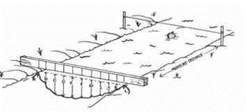
•Pipeline or Penstock:
The length, diameter, and type of pipe must be determined to predict losses due to friction.
•Transmission Distance:
This affects the generation voltage and type required and wire size needed to keep losses acceptable.
•System Voltage:
Many factors affect voltage, such as system capacity and transmission distance. Power is usually generated at battery voltage.
Where transmission distances are too great, higher voltages can be generated and transformers effectively used to step down battery voltage.
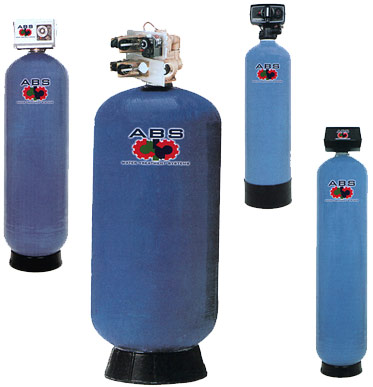
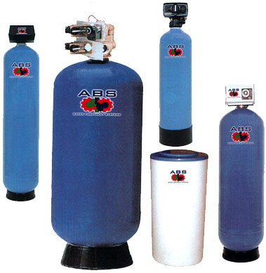
Assuring clean water as your source for power is rather important.
Some creeks have a lot of leaf or other debris, some may be shallow and sandy.
Running a turbine without a filter for even a short time could suck in material which could settle in your pipe or block your jet.
A blocked jet can cause water hammer which could damage your installation. Therefore your intake filter is important.
A larger filter with lots of holes is not so likely to suck in debris or cause a swirling eddy which pulls in debris.
Vortex action may be worsened if it is too close to the surface and if too close to the bottom it may suck in sediment.
Make filters out of material which won't corrode. The area of all the holes in total should be at least 10 times the diameter area of the pipe.
The diameter of each filter hole should be less than the smallest nozzle or jet you plan to use on the turbine.
If your turbine does not initially perform as expected we suggest you remove the filter temporarily to see if this makes a difference.
If it does, you need a larger filter or more holes in it. Use your imagination
Penstock measurement is easy.
Simply run a tape measure between your intake and turbine locations, following the route you'll use for your pipeline.
The penstock or pipe line is often made of plastic - either PVC or polyethylene. PVC pipe should be buried for protection from the sun's ultraviolet rays, polyethylene & cast iron should be buried for protection from falling trees, rocks or machines.
Also, if air temperatures normally stay below -5C for more than five days at a time, the pipeline should be buried or insulated.
Head Loss refers to the loss of water power due to friction within the penstock.
Although a pipe diameter may be enough to carry all the water flow in the design - the pipe sides, joints and bends create drag as the water passes, therefore slowing it down and effectively lowering the Head and resulting in less water pressure at the turbine.
The effects of head loss can only be measured when water is flowing. Larger pipes are less friction but add more cost.
Turbine generator units are available from a number of sources.
The choice of unit depends on a number of factors such as power line distance, desired equipment reliability, desired voltage and/or current type and cost.
Power can be generated as AC or DC but DC has increased line loss and installation expense.
In a typical situation where periodic inspection and minor maintenance is possible, the alternator system is most common.
Electricity can be fed directly to the grid or stored in your own battery bank.
The user is free to make changes to the turbine nozzle size to suit power requirements and or flow conditions.
The size of the battery bank is determined by the anticipated loads, the available charging power and the budget.
A small bank might consist of one deep cycle battery or 1 or 2 car batteries with a capacity in the range of 200 amp hours providing sufficient power for a small weekend cabin while a large installation may be made up of 12 six volt cells wired to produce 12 or 24 volts with a capacity of over 1000 amp hours.
Deep cycle batteries have been central to DC power systems and store energy for periodic surges and long term draw needed by various electrical loads.
Automobile batteries have been used also but more may be required.
TAP Green Batteries are now available. They have faster recharging times, high storage capacity, longer life, no toxic gas production and no lead/acid concerns – to name a few of the environmentally positive attributes.
Control and monitoring of battery voltage is important to prevent damage from over charging or from accidental discharge.
The monitoring equipment consists of indicator meters or lights to inform the user of system status, and the control unit maintains an optimum voltage on the battery by either regulating the generator output or by shunting power to alternate loads such as heating domestic hot water.
Powerful DC to AC inverters are used to produce high quality 110 volt AC directly from the battery bank.
These units are available in sizes from 125 watts up to 5000 watts and operate at over 90 percent efficiency.
They are fully protected against any abnormal operating conditions and take virtually no power when in an idle mode.
There are many types of turbines to choose from and we will show you a few of them as well as a bit of their history and development.
Your choice of turbine will depend on your water source as well as other factors discussed here.
The types of hydroelectric turbines are divided into 2 distinct groups:
IMPULSE and REACTION.
The runners of Impulse turbines are not immersed in water. Water flows onto the tabs that make up the runner therefore making it move.
Reaction turbines have the runner completely immersed in water, which flows between the vanes therefore moving the drive shaft
The names indicate the point at which the water enters the wheel.
If you face the water wheel from the side and regard it as a clock face, then the overshot would revolve in a clockwise direction while the pitch-back, the breast shot and undershot water wheels revolve in an counterclockwise direction.
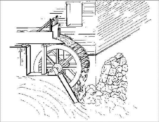
The overshot wheel is the most common wheel seen in North America.
It is a gravity wheel.
This means that it harnesses the force of gravity acting vertically on the water as it travels from the top to the bottom of the wheel.
Properly designed for the site, and correctly timed, an overshot wheel can slow the natural velocity of the falling water to as little as 10% of what it would be if the wheel was not there.
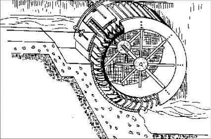
An undershot water wheel is an impulse wheel as it pushes the water. If a hillside is steep, the water moves fast at the bottom and can push strongly against the paddles of an undershot wheel.
The average overshot wheel was far more efficient than the undershot, about 65% as opposed to 25%.
When the head, or fall of water was not sufficient for a large diameter overshot wheel, the breast wheel could be used.
This is halfway between the overshot and undershot wheels.
Water strikes the buckets of the breast wheel about midway between top and bottom, using the weight of the water for a 90 degree segment of arc.
While more efficient than the undershot, their efficiency is far less than the overshot, which uses the weight of the water for a full 180 degrees.
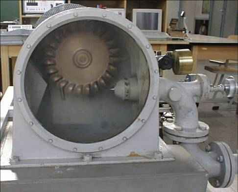
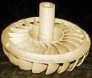
The original and classic microhydro turbine design is the Pelton.
Invented in the 19th century by directing water jets used in hydraulic mining onto overshot water wheels, it provided a way to get the high rotating speeds necessary for electrical generation.
It is used for low flow battery-charging systems, where the head is over 30 feet or so. It requires at least ten feet of head.
The Turgo runner is a refinement of the Pelton, where the jets direct water at the runner at an angle.
The Turgo is used especially for situations with high water flows; the design allows for larger jets.
Because Turgos can use more water, significant power can be generated with less head, this results in shorter penstocks
•In addition the Turgo is rugged and can be used as a small and inexpensive turbine for the right kind of site, making it a commonly used turbine.
BANKI
It is also called CROSS-FLOW and it is an impulse two-stage turbine.
Water goes into the turbine via a distribution system and it arrives at a first stage of the rotor functioning almost totally submerged.
Subsequently, the water flow changes direction and reaches the second stage of the turbine, which is totally an impulse stage.
The rotor of the turbine is formed by parallel disks, among which the blades are installed, characterized by bent tongues.
The form of the rotor is similar to the one of a tangential ventilation system.
The easy construction of the turbine allows to produce it in developing countries too.
The efficiency of this turbine is less than 87%, keeping almost constant till low flow rates (>16%).
BANKI turbines are used for water heads from 5 to 200m.
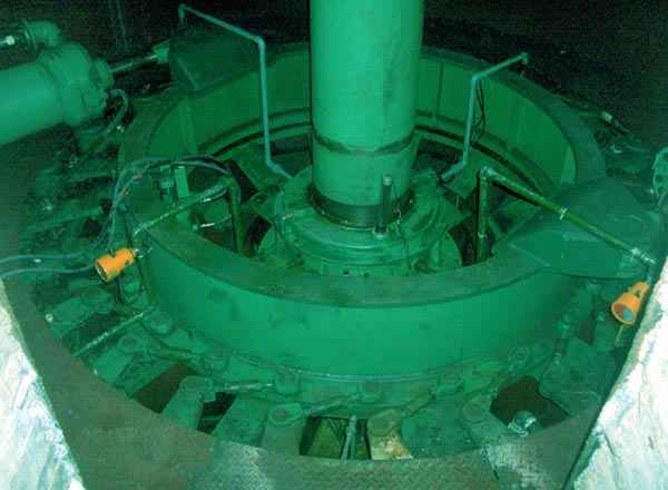
It is a reaction turbine, in which water moves as in a pressure pipe.
In fact, thanks to the adjustable nozzle blades, water is carried to the fixed blades rotor, to which it gives energy without coming into contact with the external air.
In this type of turbine the water flow is almost always radial while the outlet is axial.
FRANCIS turbines are used for water heads from 10 to 350m
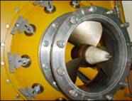
They are reaction turbines and they are divided into two types:
double (true KAPLAN) or single (semi-KAPLAN) regulation.
In the first type both the rotor and the nozzle blades are adjustable.
In the second type only the rotor blades are adjustable while the others are fixed.
The possibility of adjusting the nozzle and the rotor blades allows one to regulate the functioning of the system according to the flow rate and the water head.
In case of constant flow rate the turbine can also be formed by fixed blades to reduce costs. KAPLAN turbines are used for water heads from 2 to 20m.
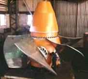
It is a reaction turbine and it is similar to the submerged part of a big outboard motor.
It is specifically used to exploit the wave-motion of the tides or the submarine currents.
The rotor of the BULB TURBINE derives from the one of the KAPLAN TURBINE.
The generator and the multiplier are contained in a waterproof case immersed in the water.
The main characteristics of this technology are the following ones:
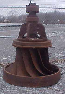
use of grids with big holes thanks to the capacity of the Archimedean screw to accept alluvial material and waste of big dimensions;-no combs and therefore no production of waste to be disposed of;-perfect compatibility with fishes;
low costs of the plant and its management.
Archimedean screw turbines are used for water heads from 1 to 10m and water flow rates from 0,5 to 5,5 m³/sec.
The most important characteristic of these turbines is that they continue to function also with minimum water flow rates.
Therefore, they are very proper for irregular water quantities.
------------------------------------------------------------------------------------------------
Hydroelectric Scheme
What is hydro-power
Hydro-Power is energy gained from the natural movement of water.
It harnesses its energy yield from moving or falling water.
Hydro-Power is a mature renewable energy technology and at present it supplies around one quarter of the worlds energy.
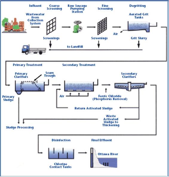
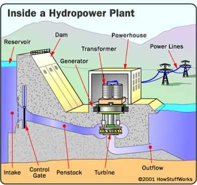
How does it work
The hydro-power scheme does not use fuel or emit pollutants and has low operating and maintenance costs.
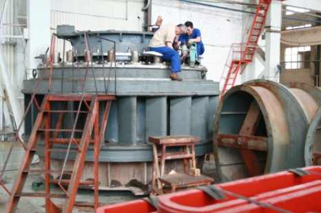
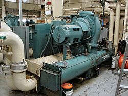
As the diagram above shows, the hydro scheme is fed by the water of the middle reservoir using the water pressure of the existing dam structure from which water is piped to our turbine house.
The turbine then turns the shaft that rotates a set of magnets past copper coils in a generator to produce electricity.
The power house transmits electricity to local businesses who buy the power from us.
The water is then discharged back into the By-wash stream via a short open tailrace.
Economic Benefits to the Community
- Has already created employment for a maintenance supervisor
- Promotes Renewable Energy
- Adds to the sustainability of Creggan Country Park
- Income generated by the hydro-scheme is used to off-set annual charges & surplus
income is reinvested back into future developments at Creggan Country Park
- Regeneration of Local Tourism. Stimulation of local economy through increased
visitor usage and educational visits.
Hydro-Power schemes are designed in accordance to the geographic character of each site, or in technical terms “the head”, which is the distance between the water inlet and outlet levels.
The measurements below are used to determine the type of hydro-electric plant suitable to a specific site:
150m High Head
20-150m Medium Head
20m Low Head
The power output is calculated by the following formula:
Power (Kw) = 8 x Head (m) x Flow (m³/sec)
-----------------------------------------------------------------------------------------------------------How to measure water head
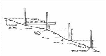
Measuring Head
Head is water pressure, created by the difference in elevation between the intake of your pipeline and your water turbine.
Head can be measured as vertical distance (feet or meters)
or
as pressure (pounds per square inch, newtons per square meter, etc.).
Regardless of the size of your stream, higher head will produce greater pressure—and therefore higher output—at the turbine.
An altimeter can be useful in estimating head for preliminary site evaluation, but should not be used for the final measurement.
It is quite common for low-cost barometric altimeters to reflect errors of 150 feet (46 m) or more, even when calibrated.
GPS altimeters are often even less accurate.
Topographic maps can also be used to give you a very rough idea of the vertical drop along
a section of a stream’s course.
But only two methods of head measurement are accurate enough for hydro system design
—direct height measurement and water pressure
.
Direct Height Measurement
To measure head, you can use a laser level, a surveyor’s transit, a contractor’s level on a tripod, or a sight level (“peashooter”).
Direct measurement requires an assistant.
One method is to work downhill using a tall pole with graduated measurements.
A measuring tape affixed to a 20-foot (6 m) section of PVC pipe works well.
After each measurement, move the transit, or person with the sight level, to where the pole was, and begin again by moving the pole further downhill toward the generator site.
Keep each transit or sight level setup exactly level, and make sure that the measuring pole is vertical.
Take detailed notes of each measurement and the height of the level.
Then, add up the series of measurements and subtract all of the level heights to find total head.
-------------------------------------------------------------------------------------------------------
Water Pressure Measurement
If the distance is short enough, you can use one or more garden hoses or lengths of flexible plastic tubing to measure head.
This method relies on the constant that each vertical foot of head creates 0.433 psi of water pressure (10 vertical feet creates 4.33 psi).
By measuring the pressure at the bottom of the hose, you can calculate the elevation change.
Run the hose (or tubing) from your proposed intake site to your proposed turbine location.
If you attach multiple hoses together, make sure that each connection is tight and leak free.
Attach an accurate pressure gauge to the bottom end of the hose, and completely fill the hose with water.
Make sure that there are no high spots in the hose that could trap air.
You can flush water through the hose before the gauge is connected to force out any air bubbles.
If necessary, you can measure total head over longer distances by moving the hose and taking multiple readings.
Keep in mind, however, that there is less than 1/2 psi difference for every vertical foot.
Except for very steep hillsides, even a 100-foot hose may drop only a few vertical feet.
The chance for error significantly increases with a series of low-head readings. Use the
longest possible hose, along with a highly accurate pressure gauge.
------------------------------------------------------------------------------------------------------
Computing Net Head
By recording the measurements described in the previous sections, you have determined gross head—the true vertical distance from intake to turbine, and the resulting pressure at the bottom.
Net head, on the other hand, is the pressure at the bottom of your pipeline when water is actually flowing to your turbine.
This will always be less than the gross head you measured, due to friction losses within the pipeline.
You will need to have water flow figures (described in the following sections) to compute net head.
Longer pipelines, smaller diameters, and higher flows create greater friction.
A properly designed pipeline will yield a net head of 85 to 90 percent of the gross head you measured.
Net head is a far more useful measurement than gross head and, along with design flow, is used to determine hydro system components and electrical output.
Here are the basics of determining pipe size and net head, but you should work with your turbine supplier to finalize your pipeline specifications.
Head loss refers to the loss of water power due to friction within the pipeline (also known as the penstock).
Although a given pipe diameter may be sufficient to carry all of the design flow, the sides, joints, and bends of the pipe create drag as the water passes by, slowing it down.
The effect is the same as lowering the head—less water pressure at the turbine.
Head loss cannot be measured unless the water is flowing.
A pressure gauge at the bottom of even the smallest pipe will read full psi when the water is static in the pipe.
But as the water flows, the friction within the pipe reduces the velocity of the water coming out the bottom.
Greater water flows increase friction further.
Larger pipes create less friction, delivering more power to the turbine.
But larger pipelines are also more expensive, so there is invariably a trade-off between head loss and system cost.
Size your pipe so that not more than 10 to 15 percent of the gross (total) head is lost as pipeline friction.
Higher losses may be acceptable for high-head sites (100 feet plus), but pipeline friction losses should be minimized for most low-head sites.
The length of your pipeline has a major influence on both the cost and efficiency of your system.
The measurement is easy,though.Simply run a tape measure between your intake and turbine locations,followingthe route you’ll useyou’re your pipeline.
Remember that you want to run the pipeline up out of the creek bed,when possible,to avoid damage during high water.
------------------------------------------------------------------------------------------
How to measure water flow
Measuring Flow
The second major step in evaluating your site’s hydro potential is measuring the flow of the stream.
Stream levels change through the seasons, so it is important to measure flow at various times of the year.
If this is not possible, attempt to determine various annual flows by discussing the stream with a neighbor, or finding U.S. Geological Survey flow data for your stream or a nearby larger stream.
Also keep in mind that fish, birds, plants, and other living things rely on your stream for survival. Never use all of the stream’s water for your hydro system.
Flow is typically expressed as volume per second or minute.
Common examples are gallons or liters per second(orminute),and cubic feet or cubic meters per second(orminute).Each can be easily converted to another,as follows:
1 cubic foot = 7.481 gallons
1 cubic meter = 35.31 cubic feet
1 cubic meter = 1,000 liters
Three popular methods are used for measuring flow—container, float, and weir.
Each will be described in detail below.
Container Fill Method
The container fill method is the most common method for determining flow in micro hydro systems.Find a location along the stream where all the water can be caught in a bucket.
If such as pot doesn’t exist,build a temporary dam that forces all of the water to flow through a single outlet.
Using a bucket or larger container of a known volume,use a stopwatch to time how long it takes to fill the container.
Then divide the container size by the number of seconds.
For example, if your container is a 5-gallon paint bucket and it takes 8 seconds to fill, your flow is 0.625 gallons per second (gps) or 37.5 gallons per minute (gpm).
Float Method
The float method is useful for large streams if you can locate a section about 10 feet (3 m) long where the stream
is fairly consistent in width and depth.
Step1.
Measure the average depth of the stream. Select a board able to span the width of the stream and mark it at 1-foot(0.3m) intervals.
Lay the board across the stream, and measure the stream depth a teach 1-foot interval.
To compute the average depth, add all of your measurements together and divide by the number of measurements you made.
Step2.
Compute the area of the cross-section ou just measured by multiplying the average depth you just computed by the width of the stream.
For example, a 6-foot-wide stream with an average depth of 1.5 feet would yield a cross-sectional area of 9 square feet.
Step 3.
Measure the speed. A good way to measure speed is to mark off a 10-foot (3 m) length of the stream that includes the point where you measured the cross-section.
Remember, you only want to know the speed of the water where you measured the cross-section, so the shorter the length of stream you measure, the better.
Use a weighted float that can be clearly seen—an orange or grapefruit works well. Place it well upstream of your measurement area, and use a stopwatch to time how long it takes to travel the length of your measurement section.
The stream speed probably varies across its width, so record the times for various locations and average them.
Weir Method
A weir is perhaps the most accurate way to measure small- and medium-sized streams.
All the water is directed through an area that is exactly rectangular, making it very easy to measure the height and width of the water to compute flow.
This kind of weir is a temporary dam with a rectangular slot, or gate.
The bottom of the gate should be exactly level, and the width of the gate should allow all the water to pass through without spilling over the top of the dam.
A narrower gate will increase the depth of the water as it passes through, making it easier to measure.
The depth measurement is not taken at the gate itself because the water depth distorts as it moves through the gate.
Instead, insert a stake well upstream of the weir gate and make the top of the stake exactly level with the bottom of the weir gate. Measure the depth of the water from the top of the stake.
Once the width and depth of the water are known, a weir table is used to compute the flow.
The weir table shown here is based on a gate that is 1 inch (25 mm) wide.
Simply multiply the table amount by the width (in inches) of your gate.
For example, assume your weir gate is 6 inches wide, and the depth of the water passing over it is 71/2 inches.
On the left side of the table, find “7” and move across the row until you find the column for “+1/2”. The table shows 8.21
cfm flow for a 1-inch gate with 71/2 inches of water flowing through it. Since your gate is 6 inches wide, simply multiply the 8.21 by 6 to get 49.26 cfm.
A weir is especially effective for measuring flow during different times of the year. Once the weir is in place, it is easy to quickly measure the depth of the water and chart the flow at various times.


![[MSF+3.jpg]](https://2img.net/h/4.bp.blogspot.com/_SynCnHGx75g/Shl2T3oVhsI/AAAAAAAAAEY/_7oem5pvQ3I/s1600/MSF%2B3.jpg)