Admin
Admin

عدد المساهمات : 3762
تاريخ التسجيل : 15/09/2009
العمر : 56
الموقع : مصر
 | موضوع: طريقة فصل الزيوت والبترول عن المياه باستخدام طريقة الفصل الاهتزازى بالاغشية البوليميرية  الإثنين فبراير 07, 2011 1:57 pm الإثنين فبراير 07, 2011 1:57 pm | |
| Petroleum Wastewater - Desalter Case Study
New Research has developed an innovative and rugged ultrafiltration membrane
system for the treatment of desalter effluent.
In the past, desalter effluent has been something that a refinery has just put up with and tried to manage as best it can
.
Now by utilizing the proprietary VSEP Filtration System, desalter effluent can be treated and mitigated at the source.
Crude Oil Basics
Crude oils are complex mixtures containing many different hydrocarbon compounds that vary in appearance and composition from one oil field to another.
Crude oils range in consistency from water to tar-like solids, and in color from clear to black. An "average" crude oil contains about 84% carbon, 14% hydrogen, 1%-3% sulfur, and less than 1% each of nitrogen, oxygen, metals, and salts
.
Refinery crude base stocks usually consist of mixtures of two or more different crude oils.
Crude oils are also defined in terms of API (American Petroleum Institute) gravity. A crude with a high API gravity are usually rich in paraffins and tend to yield greater proportions of gasoline and light petroleum products.
Crude oils that contain appreciable quantities of hydrogen sulfide or other reactive sulfur compounds are called "sour." Those with less sulfur are called "sweet.
"
All crude oils are assayed and valued depending on their potential yield.
Crude Oil with low assay numbers is referred to as "Opportunity Crude".
This type of oil will be more difficult to process due to higher levels of contaminants and water.
This type of crude will typically give desalter equipment the most trouble and require the greatest skill of the operator.
Desalting - The First Step in Crude Oil Refining
Desalting and dewatering of crude oil upstream of the crude distillation unit is a key process operation for the removal of undesirable components from crude oil before it reaches any of the major unit operations.
The operation of a desalting system can be very challenging due to changing process variables. At best, it is a process of measuring trade-offs and compromises.
A delicate balance must be maintained while controlling mixing intensity, wash water quality, chemical demulsifier feed and other parameters that can provide optimal salt removal.
On one hand the quality of the crude overflow must be within specific standards and on the other hand the under-carry must not be so potent that it compromises the system's dehydration abilities or fouls up downstream wastewater treatment.
New legislative demands placed on effluent water quality present the operator with a difficult challenge.
Optimizing the desalting process under constantly varying conditions is a key ingredient to success of the entire refinery operation.
The main function of the Desalter is to remove salt and water form the crude oil
.
However, many other contaminants such as clay, silt, rust, and other debris also need to be removed.
These can cause corrosion and fouling of downstream equipment when deposited on heat transfer surfaces. Also, there are metals that can deactivate catalysts used in the process of refining.
Desalter Theory
The Desalter removes contaminants from crude oil by first emulsifying the crude oil with chemicals and wash water to promote thorough contact of the water and oil.
The salts containing some of the metals that can poison catalysts are dissolved in the water phase.
After the oil has been washed and mixed as an emulsion of oil and water, demulsifying chemicals are then added and electrostatic fields are used to break the emulsion.
Desalters are sized to allow the water and oil to settle and separate according to Stoke's Law.
In addition, solids present in the crude will accumulate in the bottom of the desalter vessel. The desalter must be periodically washed to remove the accumulated solids.
A "mud washing" system is installed in the bottom of the vessel to periodically remove the solids.
Mud washing consists of recycling a portion of the desalter effluent water to agitate the accumulated solids so that they are washed out into the effluent
water.
These solids are then routed to the wastewater system
.
Desalter effluent or "undercarry" is a combination or many things including the mud wash done at periodic intervals, produced water that came with the crude, and the brine wash water resulting from the dilution and removal of salts and other contaminants.
Desalter Process
To accomplish desalting, the crude is first preheated to 120є-150є with heat exchangers in order to reach the required viscosity level normally in the range of 5-15 centi-stoke.
The temperature is limited by the vapor pressure of the crude-oil feedstock.
About 2-6% wash water is metered in ahead of the desalter as an extraction agent to help dissolve salts and sediments.
Intense mixing then takes place over a mixing valve.
Once in the pressurized desalter vessel, the salts and sediment settle with wash water and tend to form emulsions.
The wash water is separated by electrostatic precipitation using de-emulsifiers and acid.
The salts that are removed are mainly chlorides and carbonates.
They can cause corrosion and fouling downstream in the heat exchangers, furnaces, and distillation units, if not removed.
Electrical desalting is the application of high-voltage electrostatic charges to concentrate suspended water globules in the bottom of the settling tank.
Surfactants are added only when the crude has a large amount of suspended solids.
Other less-common processes involve filtering heated crude using diatomaceous earth and chemical treatment and settling
.
Ammonia is often used to reduce corrosion. Caustic or acid may be added to adjust the pH of the water wash
.
Wastewater and contaminants are discharged from the bottom of the settling tank to the wastewater treatment facility
.
The desalted crude is continuously drawn from the top of the settling tank and sent to the crude distillation tower
.
A properly performing desalter can remove about 90% of the salt in raw crude
.
Refinery Wastewater
The desalter effluent is a major source of contaminated wastewater and a source of hydrocarbons as oil under carry to the extent that emulsions are not completely broken.
Oil under carry can be the single largest source of oil losses to the wastewater treatment system
.
Reduction in the amount of Oil in the undercarry not only reduces sewer loadings but also recovers valuable raw material that would otherwise be lost
.
Rates vary with the water content of the crude oil and the degree of difficulty in desalting the crude, but a representative rate would be around 2-2.5 gallons of wastewater per barrel of crude oil feed to the unit
.
Desalter water contains salt, sludge, rust, clay, and varying amounts of emulsified oil (oil under carry).
Depending on the crude oil source, it may or may not contain significant levels of hydrogen sulfide (H2S), ammonia, and phenolic compounds
.
Relatively high levels of suspended and dissolved solids are usually observed
.
VSEP Membrane Filtration - Enabling Technology for Desalter Effluent
The V✧SEP, (Vibratory Shear Enhanced Process),
The most fundamental process in a refinery operation that of separation
.
Since the desalter is the first step in refining of crude oil, a bottleneck at the desalter is a bottleneck for a billion-dollar refinery asset.
In addition, the desalter will be the predominant source of wastewater in a refinery and an upset in the desalter can cause upsets in the wastewater treatment plant and put that system at risk of not meeting discharge requirements.
The current methods of desalter operation are focused on coping and adjusting with the variations in process variables that are inevitable
.
The treatment method involves a crude gravity separator combined with chemical manipulation and operator expertise.
This process is antiquated and less than desirable from a redundancy and processing point of view
.
The VSEP polymeric membrane filtration process offers an innovative, precis and utterly redundant separation technique for crude oil refining and processing.
In addition to enabling a range of very fine selective separations, use of membrane filtration results in reduced capital, chemical, operating, and energy-consumption costs. The potential for economic benefit to the user industry is revolutionary.
VSEP Desalter Treatment Process Options
There are a number of possible scenarios for filtration. During the evacuation of the desalter undercarry, the settled solids will be washed out of the system to prevent build up.
When this happens some of the rag layer emulsion comes with it. This blow down is what can give conventional chemical wastewater treatment plants trouble
.
The VSEP can be set up to handle the entire flow of the desalter effluent including both the briny salt water as well as the modulating rag layer blowdown.
Or, by using automated valves, the VSEP can be configured to handle only the rag layer blow down.
If the VSEP will handle the entire desalter effluent flow, the desalter is set to a continuous mud wash process to even out the solids loading in the feed to the VSEP.
Then the VSEP will dewater this effluent and send a concentrated sludge to the Coker
.
If the VSEP will only handle the rag layer blowdown, the mud wash operator controls destination valves accordingly.
While the desalter is just draining salt-water effluent, the waste will be sent to the existing treatment plant
.
Then just prior to a mud wash, destination valves will configure to feed the desalter effluent to the VSEP
.
After the mud wash, the valves revert back to the original position feeding the wastewater treatment plant
.
Case Study Process Conditions
The oily wastewater is fed to the VSEP treatment system at a rate of 240 gpm
.
The VSEP system will monitor tank level and will adjust based upon demand
.
The VSEP feed tank acts as a primary settling tank. It is cone bottomed and heavy solids settle quickly where they are purged
.
The feed to the VSEP is taken out of the side of the tank to eliminate excessive maintenance cleaning of a protective 60 mesh pre-screen to the VSEP
.
As the system initiates, a feed pump will spin up to a pressure of 70 psig.
Then a modulating valve will throttle the flow of the reject to a rate that will produce the desired concentration of suspended solids.
Three industrial scale VSEP units, using ultra-filtration membranes are used to treat the 240 gpm process effluent.
The concentrated reject stream is at a concentration of about 13.3% TSS and is sent to the Coker for recovery of the oil and hydrocarbons.
VSEP generates a permeate stream of about 192 gpm which is sent on to the existing wastewater treatment plant.
The permeate contains less than ~ 1 mg/L of total suspended solids (TSS), and reduced levels of total dissolved solids (TDS). Membrane selection is based on material compatibility, flux rates (capacity) and concentration requirements.
In this example, the TSS reduction is well over 99% while the oily waste is concentrated from a starting feed of 1.5-2% to a final concentrate of 13.3% by weight.
Benefits of VSEP when used for Desalter Effluent
Redundancy
The VSEP is installed as a side stream to the desalter effluent. It is used on a demand basis and will initiate automatically based upon tank level.
It offers many kinds of redundancy options in operation that are very important to refinery operations. First, the VSEP system can be bypassed completely if desired and the desalter effluent will be treated in the same manner as it is now.
Or the VSEP can handle the entire desalter flow and help to take the load off of the existing wastewater treatment, thus increasing its capacity and safety margin when it comes to discharge
.
VSEP units are modular and easy to install in parallel for complete redundancy.
Skill of the operator
The rag layer blow down is the primary cause of process upsets and the manipulation of this process requires a very skilled operator or group of operators who cannot afford to make mistakes.
The normal salty water discharge from the desalter is relatively benign and can be handled easily by existing processes.
The fact that the quality of the crude changes and that the blow downs are done at specified intervals means that this process is a constant game of tweaking and cajoling.
Installation of the VSEP with the set purpose of processing the problematic rag layer blowdown removes this process headache from the effluent operator's daily chores.
When VSEP is installed, the frequency of blowdown, the effectiveness of the demulsifiers, and the variations in the crude are unimportant and no longer pose a process upset threat
Debottlenecking the facility
Since the desalter is the first step in refining of crude oil, it is critical that this piece of equipment be consistent and reliable
.
Because oil is superheated and pressurized during refining, it is not a process that you can just turn off with a switch
.
Shut downs can take hours or days to complete. In addition, the profitability of the refinery depends on getting maximum use out of the refinery asset and personnel on staff.
Process upsets cannot be tolerated. The desalter has been identified as a very significant threat for bottlenecking the entire refinery operation including the refining of oil and the wastewater treatment that comes from it
.
Installation of VSEP can mitigate or eliminate the possibility of desalter bottleneck. VSEP is a redundant and effective tool that can be used to reduce process risk
.
Reduce the load on wastewater treatment
The desalter can be the primary source of wastewater to the wastewater treatment plant.
The desalter operator must constantly be careful about the discharge of the desalter so that the treatment plant is not overloaded or unable to handle the hazardous materials that come from the desalter.
Sometimes this can mean lesser quality desalted crude is produced as a trade off to not swamping the treatment plant
.
Desalter effluent is the primary source of oil to the treatment plant.
Many times the existing wastewater treatment plant is at capacity and the amount of overdesign and safety factor is marginal
.
VSEP is a very effective tool that can be used to control the load on the treatment plant. Since the VSEP can take the rag layer blow down out of the wastewater loop and send it to the Coker, this alone reduces the load significantly.
The VSEP can also be configured to handle the entire desalter effluent further reducing the load on the treatment plant.
The VSEP can also be configured to handle the desalter effluent completely and bypass the existing treatment plant. These options give process engineers ultimate ability to maximize the use and capacity of the existing wastewater treatment facility.
Oily Wastewater
Oil/Water separation covers a broad spectrum of industrial
process operations.
There are many techniques employed
depending on the situation.
The oily wastewater application can be broken
down into categories determined by the type of user and the
oil/ water separation desired.
Types of V✧SEP Oily Wastewater customers:
Manufacturing where oily water is a waste product
Waste haulers & recyclers
There is a saying: “Oil and Water don’t mix”. This is true
,
but they can exist as an emulsion.
Oil is not soluble in water
but it can exist evenly dispersed as globules in water.
The
concentration of these globules is a function of mixing or
stirring
. If allowed to stand the emulsion will separate
because oil is lighter than water, although, some amount of
oil globules will remain in the water
.
Another interesting
fact is that this emulsion can exist two ways.
If the
concentration of Oil is less than 50%, the water will be the
suspension fluid and the oil will be the globule
.
A phase
transition occurs if the oil content is more than 50%. When
this happens, the oil is the suspension fluid and the water
forms globules. For this reason, hydrophilic membrane
separations will be possible only when the oil content is
less than 50%.
V✧SEP
Able to produce drinking water quality filtrate from any
wastewater. Extremely energy efficient and the vertical
design allows for a very small footprint. Does not require
pre-treatment or post-treatment for that matter.
Wide range
of membranes available allow for precise separations based
on the process objectives. There is no chemical addition
required except for periodical membrane cleaning.
Suitability of V✧SEP for Oily Wastewater
As with other waste streams, volume reduction is the goal.
Hauling and disposal costs are king.
Wastewaters normally
have very strict sewering rules and surcharges are attached
to anything that is sewered.
Since Oil is normally limited to
100 ppm, oily wastewaters cannot be sewered and must be
taken care of in other ways.
Oil can also not be landfilled as
long as it is a liquid. Therefore, disposal of oily wastewater
is an expensive operation.
Volume reduction of the oily
wastewater will reduce the treatment costs to dispose of the
material.
There are also many types of membrane solutions
for oil water separation. A common membrane device used
is a tubular membrane system.
One common problem with
Tubular Membrane Systems is the permeate quality. V✧SEP
can offer competitive installed costs along with RO quality
permeate requiring less post treatment.
Typical Sewer Discharge Limits:
Nickel 4.1 mg/L
Mercury 0.0015 mg/L
Lead 1.1 mg/L
Zinc 12.7 mg/L
Silver 1.2 mg/L
Copper 4.2 mg/L
Chromium 5.0 mg/L
Cadmium 0.43 mg/L
Arsenic 0.57 mg/L
Cyanide 0.50 mg/L
Oil & Grease 100.0 mg/L
Concentration Polarization is Typical Sewer Discharge Limits:
the main limiting factor to
membrane filtration with oily
wastewaters.
Therefore the
existence of a boundary layer
of highly concentrated oil and
solids next to the membrane
surface must be eliminated
.
Spiral membranes employ
crossflow and fluid velocity
to accomplish this.
Tubular
membranes use the same
technique with greater
efficiency.
None of these has
the degree of efficiency of the
vibrating membrane surface
of V✧SEP which can use
both high crossflow velocities
as well as high vibrational energy at the membrane surface
which is oscillating back and forth 55 times per second
.
Performance comparisons based on GFD of permeate flow
is difficult because there are so many variables to consider
.
If all things are equal and the comparison is apples and
apples, V✧SEP will outperform the other membrane-based
technologies.
Permeate flow rates will vary depending on
the initial concentration of oil and other materials in the
feed material as well as the % recovery which is being
achieved.
Compact Design
The V✧SEP Machine incorporates a modular design which
makes it compact. Because the basic design is vertical rather
than horizontal, the needed floor space per unit is inherently
less than other types of separations systems.
The V✧SEP
does require up to 17’ in ceiling clearance. In most industrial
applications ceiling clearance is ample, it is floor space
which is limited.
Benefits of V✧SEP Compact Modular Design:
1] Easily added into an existing system to enhance performance
2] Can be installed in areas where space is at a premium
3] Is easily portable and can be moved from plant to plant
4] Can be installed as multiple stage systems or as single pass
5] Can be “chain linked” to an any number depending on demand
.
6] More units can be installed as production grows
.
Very often floor space is so limited, or the system being
designed is so large that a separate structure is built to
accommodate the treatment system.
In such cases, the fact
that the V✧SEP units are
vertical and compact, it may
be able to fit into an existing
area of the building or it will
reduce new building costs by
requiring less space
.
Construction costs of $80 to
$120 $/square foot for new
industrial buildings can add up
and are a consideration when
figuring the overall cost
burden of completed systems
ready to use.
In addition to the
limited space required for the
mechanical components, the
actual filter area has been
designed in such a way as to
be extremely compact and
energy efficient. In the largest model, the “Filter Pack”
contains 2000 Square Feet of membrane surface area, about
the size of a medium size house. This 2000 SF of membrane
has been installed into a container with a volume of about
15 Cubic Feet!!
Effects of Temperature
Temperature needs to be considered with regard to design
.
Temperature can be used to increase filtration performance
.
A stream that appears to be too expensive to filter at 25C
may be well within the budget for a project at 40 or 50C
even though you have a cost associated with heating the
feed.
The reason is because increased temperature decreases
the viscosity of the liquid and enables the material to flow
through the membrane faster.
It also makes it possible to
reach a higher endpoint solids because generally the material
remains more fluid at a higher temperature.
As many streams
are water-based, the following table provides the viscosity
correction factors for water at various temperatures.
Volume Reduction
With Oily wastewater, hauling for disposal
is the conventional method of remediation
.
Since hauling costs can be very expensive,
reducing the volume that needs to be
hauled can have a significant effect on
operating costs.
V✧SEP is capable of
volume reducing wastewaters by up to
98% leaving a small amount to be hauled
and clean water that can be sewered or
reused in the process.
The recovery ratio is the amount of
liquid, which is recovered as clean, permeate from the feed
flow. In other words, it is the ratio of liquid that passes
through the membrane versus what is fed to the membrane
.
This is usually a critical factor for membrane filtration
because for a product dewatering or wastewater application,
a person is generally looking to remove as much of the water
as possible.
There are two costs of higher recoveries: lower
flux rates and degraded permeate quality.
These effects are
especially prevalent when you are reaching into the high
90% range. The average flux degrades because the feed side
solids increase as you recover more and more of the water.
In our filter pack, the feed enters through a pipe in the top
of the filter module and flows in a serpentine pattern
throughout the pack.
The higher recovery does not affect
the flux at the top of the filter pack because that material is
almost always at the same concentration given a consistent
feed. However, the material at the bottom of the filter pack
will flux slower because it contains less water for removal
and more solids to impede the flow of liquid through the
membrane.
The average flux is a time weighted average
across the entire filter pack. If the flux at the bottom of the
pack becomes slower then it will in turn lower the overall
average flux.
The permeate quality degradation occurs in
the tighter ultrafiltration, nano-filtration and RO membranes
where there is rejection number based on % of molecules or
ions in the feed.
Again as you remove more of the water,
the concentration on the feed side will increase and given
that the rejection of the membrane remains constant less
and less of the feed solids will be rejected.
Those solids
will instead be passed through the membrane into the
permeate. For example, a 90% NaCl reject membrane will
still be rejecting 90% of the dissolved solids at perhaps a
60% recovery.
However, beyond that recovery the permeate
quality will slowly deteriorate because the feed side solids
are increasing. Since 10% of the feed side solids pass
through the membrane (by definition a 90% reject
membrane), the amount of material which passes through
the membrane will increase.
This material pollutes the
permeate. When the recovery is nearly the same as the
rejection then the system behaves as if there is no membrane
.
Therefore, it is important to not only identify the membrane
and the desired recovery but also consider the economic
tradeoff between permeate quality and recovery
.
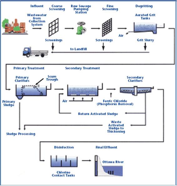
Process Conditions
A process schematic for treatment of a typical oily
wastewater process using a V✧SEP system is presented in
the figure to the right. When the residual oily wastewater
has been settled so that oil and water can separate naturally,
the result is a process effluent, at 1.5 to 2% by weight total
solids (TS). This process effluent is normally sent to a multitrain
chemical treatment step by a filter press or a dryer or an
evaporator in order to concentrate the solids to 60 to 65% by
weight. As you can see in the diagram, the addition of
V✧SEP to concentrate the process effluent improves the
process efficiency. The permeate can be reused in the process
or discharged. The oily wastewater is fed to the
V✧SEP treatment system at a rate
of 44 gpm and a pressure of 250
psig. One industrial scale V✧SEP
unit, using nano-filtration
membrane is used to treat the
process effluent.
The produced
concentrated stream at a flow rate
of 10 gpm and a solids
concentration of 10% TS is sent
to a coalescer and stored for
hauling.
V✧SEP generates a
permeate stream of about 34 gpm
which is recycled to the process
or discharged to the sewer. The
permeate concentration is reduced
to ~ 1 mg/L of total suspended
solids (TSS), and a low level of total dissolved solids (TDS),
all well below the design requirements for process recycling
or discharge.
Membrane selection is based on material
compatibility, flux rates (capacity) and concentration
requirements. In this example, the TSS reduction is over
99% while the oily waste is concentrated from a starting
feed of 1.5-2% to a final concentrate of 10% by weight.
The permeate quality from the V✧SEP can be controlled
though laboratory selection of membrane materials available
to fit the application parameters
.
Successful pilot tests have been conducted at New Logic
for many kinds of oily wastewater treatment.
Depending
on process temperatures, membrane selection and the
requirement for solids concentration or BOD/COD removal
for effluent streams, the permeate flux rate in the V✧SEP
can range from 15 to over 150 gallons per day per square
foot (GFD).
Economic Value
New Logic’s V✧SEP system provides an alternative
approach for oily wastewater treatment applications.
In a
single operation step, V✧SEP will provide concentrated oil
sludge and also reduce BOD, COD, TSS, TDS and color to
provide a high quality permeate stream for discharge or reuse
in the process. In many applications, the addition of V✧SEP
will eliminate conventional treatment process requirements
and technologies without chemical treatment demands.
The
justification for the use of V✧SEP treatment system in your
process is determined through analysis of the system cost
and benefits including:
Reduction of solids from discharge stream and the associated
treatment cost
.
Reduction of BOD, COD, TSS, TDS and color for the
effluent stream
.
Provision of high quality water for reintroduction into the
process.
Offset fresh water demands and pretreatment cost.
Retain heat in recycled process water as a possible method
to reduce energy requirements.
Elimination of biological growth, and odor in effluent
.
Simplify effluent treatment with a compact, low energy
system.
Typical makeup of Oily Wastewater:
Common Name Content
Water ~98.5%
Oil & Grease 1.50%
Zinc 100 ppm
Lead 10 ppm
Copper 70 ppm
Nickel 60 ppm
TSS 250 ppm
Typical V✧SEP Performance:
Feed Permeate
Nickel 60 mg/L ND
TOC 15,000 mg/L 50 mg/L
Lead 5 mg/L ND
Zinc 100 mg/L ND
by
colonel.dr
bahaa badr
scientific advisor
Copper 70mg/L ND
BOD 19,100 mg/L 7,640 mg/L
[u] | |
|


![[MSF+3.jpg]](https://2img.net/h/4.bp.blogspot.com/_SynCnHGx75g/Shl2T3oVhsI/AAAAAAAAAEY/_7oem5pvQ3I/s1600/MSF%2B3.jpg)