Admin
Admin

عدد المساهمات : 3762
تاريخ التسجيل : 15/09/2009
العمر : 56
الموقع : مصر
 | موضوع: Design and Construction of Water Wells/اسس تصميم وبناء ابار مياه الشرب  السبت مارس 03, 2012 4:48 pm السبت مارس 03, 2012 4:48 pm | |
|
Design and Construction of Water Wells
BY
GENERAL,DR
BAHAA BADR
TECHNILAB EL-BAHAA GROUP
Choosing a drilling contractor
| Choosing a well site
| Well design considerations
| Well completion
The initial investment for a properly designed and constructed well pays off by ensuring:
A reliable and sustainable water supply consistent with your needs and the capability of the aquifer
Good quality water that is free of sediment and contaminants
Increased life expectancy of the well
Reduced operating and maintenance costs
Ease of monitoring well performance.
Although you need to hire a drilling contractor to design, drill and construct the well and choose the appropriate materials, it is important for you to know what is going on.
You can then work with the drilling contractor to ensure you get the well design you need.
Choosing a Drilling Contractor
Choose a drilling contractor who has experience in your area. Provincial regulation requires that they have an approval to drill water wells. A list of approval holders is available through Alberta Environment.
Either you or the drilling contractor should complete a survey of existing wells in your area. It will provide important information about:
Typical yields and water quality
Which aquifer to tap into
Trends in well construction methods
Prior drilling success rates.
A drilling contractor cannot always determine in advance the depth at which an adequate water supply will be found. Neighboring wells offer some guidance but not a definite assurance.
Surveys of existing wells are available for a nominal fee from the Groundwater Information Centre.
In some areas of Alberta, regional groundwater assessment studies are also available and may identify aquifer potential and groundwater quality.
Also check with neighbors about their experiences with well performance, well maintenance and water quality changes.
Choosing a Well Site
Your choice of well site will affect the safety and performance of your well.
As you examine various sites, remember to consider any future development plans for your farm or acreage such as barns, storage sheds and bulk fuel tanks. You must also consider provincial regulations that dictate well location.
Most contaminants enter the well either through the top or around the outside of the casing. Sewage or other contaminants may percolate down through the upper layers of the ground surface to the aquifer.
The following criteria are intended to prevent possible contamination of your well and the aquifer. It is both your and the driller’s responsibility to ensure that:
The well is accessible for cleaning, testing, monitoring, maintenance and repair
The ground surrounding the well is sloped away from the well to prevent any surface run off from collecting or ponding
The well is up-slope and as far as possible from potential contamination sources such as septic systems, barnyards or surface water bodies
The well is not housed in any building other than a bona fide pumphouse.
The pumphouse must be properly vented to the outside to prevent any buildup of dangerous naturally occurring gases
The well is not located in a well pit.
Provincial regulations outline specific drilling and construction requirements as well as licensing procedures for groundwater diversion and use.
Minimum distance requirements
Provincial regulations outline minimum distance requirements as follows. Equivalent imperial distances in feet are rounded up to nearest foot.
The well must be:
10 m (33 ft.) from a watertight septic tank
15 m (50 ft.) from a sub-surface weeping tile effluent disposal field or evaporation mound
50 m (165 ft.) from sewage effluent discharge to the ground
100 m (329 ft.) from a sewage lagoon
50 m (165 ft.) from above-ground fuel storage tanks
3.25 m (11 ft.) from existing buildings
2 m (7 ft.) from overhead power lines if:
the line conductors are insulated or weatherproofed and the line is operated at 750
volts or less
6 m (20 ft.) from overhead power lines if the well:
does not have a pipe and sucker rod pumping system
has a PVC or non-conducting pipe pumping system
has well casing sections no greater than 7 m (23 ft.) in length
12 m (40 ft.) from overhead power lines for all other well constructions
500 m (1,641 ft.) from a sanitary landfill, modified sanitary landfill or dry waste site.
The installation of a leaching cesspool is no longer permitted.
It is, however, highly recommended that any newly constructed water well be located at least 30 m (100 ft.) from any existing leaching cesspool.
Well Design Considerations
Well design and construction details are determined after a test hole has been completed and the geological zones have been logged.
There are many components to well design the driller must take into account. Decisions will be made about:
Well depth
Type of well
Casing material, size and wall thickness
Intake design
Formation seal
Monitoring and preventive maintenance provisions.
Wells that require licensing cannot be constructed with a multi-aquifer completion.
Well depth
During the test hole drilling, the drilling contractor will complete a formation log.
Soil and rock samples are taken at various depths and the type of geologic material is recorded.
This allows the driller to identify aquifers with the best potential for water supply.
Some drillers also run an electric or gamma-ray log in the test hole to further define the geology.
This gives them more accurate information about aquifer location.
Generally a well is completed to the bottom of the aquifer.
This allows more of the aquifer to be utilized and ensures the highest possible production from the well.
Types of wells
There are two main types of wells, each distinguished by the diameter of the bore hole. The two types are bored wells and drilled wells.
Bored wells
A bored well is constructed when low yielding groundwater sources are found relatively close to the surface, usually under 30 m (100 ft.).
Bored wells are constructed using a rotary bucket auger.
They are usually completed by perforating the casing or using a sand screen with continuous slot openings
One advantage of bored wells is the large diameter of the casing, from 45-90 cm (18-36 in.).
It provides a water storage reservoir for use during peak demand periods.
A disadvantage of utilizing a shallow groundwater aquifer is that it relies on annual precipitation for recharge.
Water shortages may occur following long dry periods in summer and extended freeze up during winter months.
Drilled wells
Drilled wells are smaller in diameter, usually ranging from 10-20 cm (4-8 in.), and completed to much greater depths than bored wells, up to several hundred metres.
The producing aquifer is generally less susceptible to pollution from surface sources because of the depth.
Also, the water supply tends to be more reliable since it is less affected by seasonal weather patterns.
There are two primary methods of drilling:
Rotary
Cable tool.
Rotary drilled wells are constructed using a drill bit on the end of a rotating drillstem.
Drilling fluid or air is circulated down through the drillstem in the hole and back to the surface to remove cuttings. Rotary drilling rigs operate quickly and can reach depths of over 300 m (1000 ft.), with casing diameters of 10-45 cm (4-18 in.).
Cable tool drilled wells are constructed by lifting and dropping a heavy drill bit in the bore hole.
The resulting loose material, mixed with water, is removed using a bailer or sand pump.
This method, also called percussion drilling, reaches depths up to 300 m (1000 ft.).
Well diameters can range from 10-45 cm (4-18 in.). The drilling rate is typically much slower than for a rotary rig, but when aquifers are low yielding, they may be more easily identified using this method.
There are three types of possible well completions for both drilling methods
Surface casing with slotted or perforated liner
Sand screen with continuous slot openings
Single string slotted or perforated casing.
Casing size and type
Decisions about the diameter and type of well casing are made after the driller considers the following:
Aquifer characteristics
Hydraulic factors that influence well performance
Drilling method
Well depth
Cost
The casing must be large enough to house the pump and allow sufficient clearance for installation and efficient operation.
If a submersible pump is going to be used, the casing must have an inside diameter of at least 10.16 cm (4 in.), by law.
It is recommended that the casing be at least one nominal size larger than the outside diameter of the pump.
The more space there is between the pump and the casing, the easier it will be to service and repair the pump in the future.
There are two common materials used for casing:
steel and plastic.
Steel casing is the strongest but is susceptible to corrosion.
Plastic casing is becoming more popular because of its resistance to corrosion.
All casing must be new and uncontaminated.
Plastic casing must be made of virgin resin, not recycled material.
Materials used in the drilling and construction of water wells must be new and uncontaminated.
Intake design
Water moves from the aquifer into the well through either a manufactured screen or mechanically slotted or perforated casing.
Screens are manufactured with regularly shaped and sized openings.
They are engineered to allow the maximum amount of water in with minimal entry of formation sediments.
Stainless steel screens are the most widely used because they are strong and relatively able to withstand corrosive water.
Screens are manufactured with various slot sizes and shapes to match the characteristics of the aquifer.
Slotted or perforated casing or liner is made by creating openings using a cutting tool ordrill. Pre-slotted plastic pipe is also available.
Slot openings and perforations are spaced further apart than screen openings.
This reduces the amount of open area to allow water into the well. The openings tend to vary in size and may have rough edges depending on how they were made.
This impedes the flow of water into the well and may not hold back the formation sediments.
The drilling contractor examines the cuttings from the borehole and makes a judgement whether to use a screen, or slotted or perforated casing/liner.
While a screen is the more expensive alternative, it is necessary if the aquifer is composed of loose material such as fine sand, gravel or soft sandstone.
A slotted or perforated casing/liner can be used when the aquifer formation is more consolidated, such as hard sandstone or fractured shale.
After a choice is made between a screen, or slotted or perforated casing/liner other decisions will be made regarding:
Size of slot opening
Total area of screen or perforation that is exposed to the aquifer
Placement of the screen or perforations within the aquifer.
Ensure that the pumping water level in the well never goes below the top of the slot openings or perforations.
This will prevent oxygen exposure to the aquifer which would enhance bacterial growth and reduce well yield.
Slot size openings
The slot openings must be small enough to permit easy entry of water into the well while keeping out sediment.
The slot size chosen will depend on the particle size of the earth materials in the producing aquifer.
Typically a drilling contractor will select a slot size that allows 60 percent of the aquifer material to pass through during the well development phase of drilling.
The remaining 40 percent, comprising the coarsest materials, will form a natural filter pack around the perforations or screen.
Total open area of screen
The total area of the slot openings is dependent on the length and diameter of the screen. While the length of the screen is variable, the diameter of the screen is determined by the diameter of the well casing.
The yield from a well increases with an increase in screen diameter but not proportionately so. Doubling the screen diameter raises the well capacity only 20 percent.
The amount of open area of the screen or slotted or perforated casing/liner must be calculated to ensure the water from the aquifer does not enter the well too quickly.
A larger amount of open area allows the water to enter the well at a slower rate, causing a lower drop in pressure in the water as it moves into the well.
If the water flows too quickly, there will be problems with incrustation.
Incrustation is a buildup that occurs when dissolved minerals in the groundwater come out of solution and deposit on the screen or casing.
As a result, the perforations get plugged and water cannot enter the well at the same rate, and the yield from the well will be reduced.
The pore spaces in the aquifer immediately adjacent to the perforations may also get plugged with fine material which could result in yield reduction.
Placement in the aquifer
The screen or perforations on the casing/liner must be placed adjacent to the aquifer.
If improperly placed, the well may produce fine sediment which will plug plumbing fixtures and cause excessive wear on the pump.
If the driller uses geophysical logging equipment to accurately identify the boundaries of the aquifer, the exact placement will be easier.
Annulus seal
Sealing the well protects the well’s producing zone from contamination.
The diameter of the bore hole is usually slightly larger than the casing being installed.
The space between the bore hole and the casing is called the annulus of the well.
It must be sealed to prevent any surface contamination from migrating downward and contaminating the water supply.
It also prevents any mixing of poor quality aquifers with the producing aquifer of the well .
Provincial regulations require the annulus be filled with impervious material such as cement or bentonite.
To isolate the producing zone of the well, the annulus is filled from immediately above the perforated zone to the ground surface.
Once the well has been drilled and the equipment is in place, there are several procedures the drilling contractor must complete before the well is ready to use.
The drilling contractor is responsible for:
Well development
Disinfecting the well
Conducting a yield test.
Well development
Well development is the process of removing fine sediment and drilling fluid from the area immediately surrounding the perforations.
This increases the well’s ability to produce water and maximize production from the aquifer.
Jetting, surging, backwashing and overpumping are methods used to develop a well. Water or air is surged back and forth through the perforations.
Any fine materials that are in the formation become dislodged and are pumped or bailed from the well.
This procedure is continued until no fine particles remain and the water is clear.
Coarser particles are left behind to form a natural filter pack around the screen, slot openings or perforations.
If the aquifer formation does not naturally have any relatively coarse particles to form a filter, it may be necessary to install an artificial filter pack.
The pack is placed around the screen or perforations so the well can be developed.
For example, this procedure is necessary when the aquifer is composed of fine sand and the individual grains are uniform in size.
It is important to match the grain size of the filter material with the size of the slot openings of the screen to attain maximum yield from the well.
Typically the slot size of the screen is selected so that 85 percent of the artificial pack material remains outside of the screen.
Yield test
A yield test, often called a pump test, is important because the information gathered during the test assists the drilling contractor to determine the:
Rate at which to pump the well
Depth at which to place the pump.
Provincial regulations outline the minimum yield test for all new wells.
After drilling and developing a well, the drilling contractor must remove water from the well for at least 2 hours.
If a pump is used to remove the water, then water level measurements can be recorded as the water level draws down.
After 2 hours, water removal stops and the recovery of the water level is monitored and recorded.
Measurements must be taken at specific time intervals for a 2 hour period or until the water level returns to 90 percent of its original level.
Once the yield test is complete, the drilling contractor will decide at what rate the aquifer can be pumped without lowering the water level below the top boundary of the aquifer, the top of the perforations or below the pump intake.
The pump that is installed in the well should have a capacity equal to, or less than, the rate at which the well can supply water for an extended period of time without lowering the level below the pump intake.
That rate is considered the safe pumping rate for the well.
The yield test provides a benchmark of your well's performance.
Repeating this test at a later date can be used to assess any changing conditions of the well and determine when maintenance is required.
Disinfecting the well
Provincial regulations require the drilling contractor to disinfect new wells with chlorine.
The concentration is calculated on the volume of water that is in the well.
The concentration must be at least 200 milligrams of chlorine per litre of water present throughout the water in the well and must be left in the well for at least 12 hours to ensure any bacteria present are destroyed.
Chlorination is done after the pumping equipment is installed and before the well is put into production.
The yield test provides a benchmark of your well's performance. Repeating this test at a later date can be used to assess any changing conditions of the well and determine when maintenance is required.
| |
|
Admin
Admin
عدد المساهمات : 3762
تاريخ التسجيل : 15/09/2009
العمر : 56
الموقع : مصر
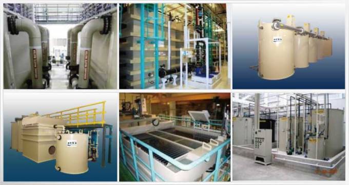
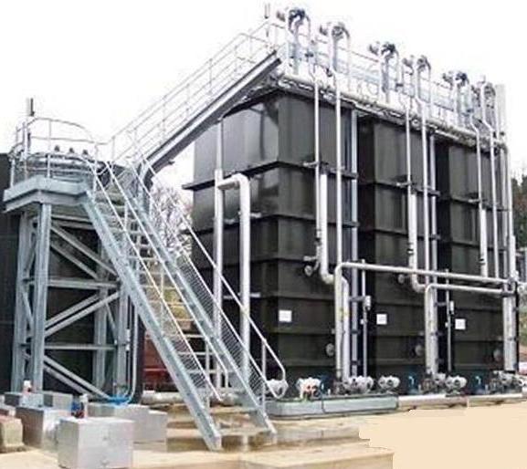
| | موضوع: صور للابار المستعملة لمياه الشرب السبت مارس 03, 2012 4:53 pm | |
| [img]  [/img] [img]  [/img] [img]  [/img] | |
|


![[MSF+3.jpg]](https://2img.net/h/4.bp.blogspot.com/_SynCnHGx75g/Shl2T3oVhsI/AAAAAAAAAEY/_7oem5pvQ3I/s1600/MSF%2B3.jpg)