Admin
Admin

عدد المساهمات : 3762
تاريخ التسجيل : 15/09/2009
العمر : 57
الموقع : مصر
 | موضوع: التخلص من الفينول والسيانيد من مياه الصرف الصناعى للمصابغ مقدمة من المهندسة نورا عبد الغفار  الإثنين ديسمبر 28, 2009 4:51 am الإثنين ديسمبر 28, 2009 4:51 am | |
|
Techno Lab Elbahaa GP
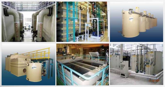
Report About :Removal Of Phenol, Nitrogen Compounds ,Hydrogen Sulfide And Cyanide From WasteWater Through Dyeing Line
By : Eng.Noura Abd EL-Ghaffar Awad
Introduced To : Dr.Bahaa Badr EL-Din
-1-
Introduction
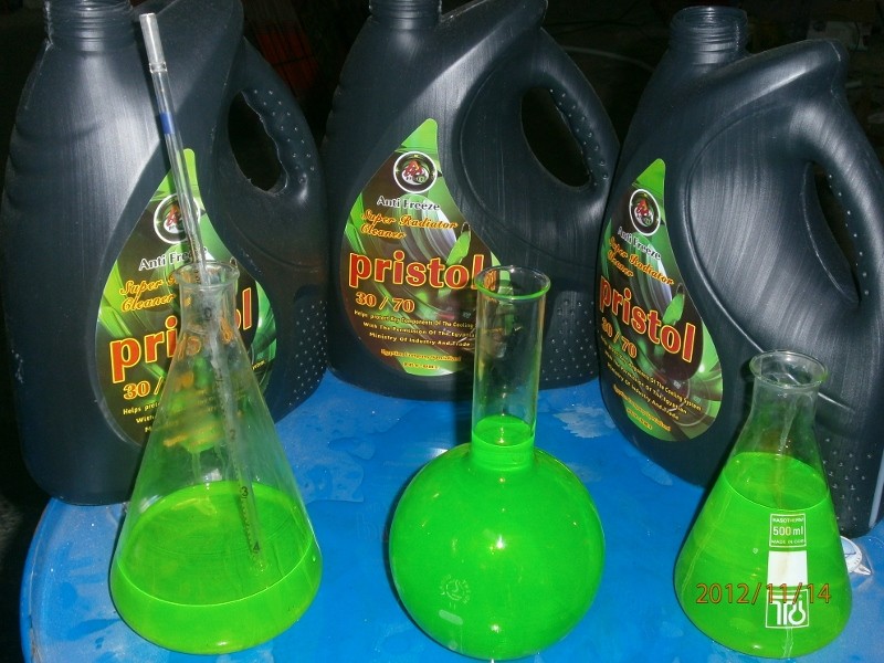
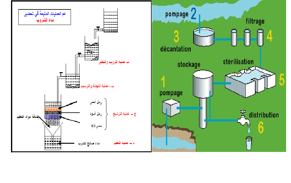
Wastewater from any industry is very important source as saving money for any project when we exploit this source well especially if it belongs to a dyeing line then we can use the wastewater again after it’s purification and those chemicals in the waste , after removing them , we can reuse them again or selling them to a neighboring companies work in asymptotic field.
Here, in my report, I had discussion about removal of those chemicals like phenol, nitrogen compounds, hydrogen sulfide and cyanide and how these methods of removing is possible.
-2-
Phenol Removal From Wastewater Through Dyeing line (1)
Pollution by phenols is an important environmental issue. Phenol, being a basic structural unit for a variety of synthetic organic compounds, wastewater originating from many chemical plants and dye manufacturing industries contain this chemical.
Phenol has been classified as hazardous pollutants because of their potential harm to human health.
The majority of phenols are toxic substances and some are known or suspected carcinogens.
It is important to remove phenols from contaminated industrial
aqueous streams before discharging
-Conventional processes for removing phenol such as :
1-Oxidation with ozone/hydrogen peroxide .
2-Ion exchange.
3-Electrochemical oxidation.
4- Reverse osmosis.
5-Photo-catalytic degradation.
6- Adsorption .
7-Solvent extraction.
8-Emulsion liquid membranes.
In my report I preferred to disscuss adsorption , solvent extraction and emulsion liquid membranes
-3-
1- ADSORPTION (2)
It’s a method of the catalytic wet air oxidation (CWAO) which permits detoxification of hazardous substances at relatively mild conditions
temperature and pressure conditions (less than 200°C and 100 bar) by using active oxidation catalysts
Likewise, a two-step adsorption-oxidation process for the treatment of aqueous phenolic effluents has also been reported. This process is based on the use of activated carbon (AC), as adsorbent in the first step as oxidation catalyst in the second step, in a single bifunctional reactor.
Adsorption technology, however, is the method currently used for removing phenols at low concentrations. For this purpose, nonspecific sorbents such as activated carbons (ACs),metal,oxides, silica, and ion exchange resins have been used as well .
The major advantage of AC adsorption is that the treated adsorbent can easily be separated from the treated liquid stream. This characteristic allows easy and flexible process operation as well as reduction in process costs.
Adsorption of phenol from the aqueous phase is a very important application of powdered and granular activatedcarbons.
The removal of phenols from aqueous solutions may be carried out using commercial ACs or ACs prepared from coconut shells.
EXPERIMENTAL
Preparation of activated carbons
The starting date pits were washed several times with water and then dried at 150°C. The dried pits were crushed and sieved, the fraction of particle size 0.5–1.0 mm being used for the preparation of activated carbon. The char was obtained by carbonization in a horizontal furnace
-4-
under a fow of nitrogen (150 ml.min–1) at 825°C with a heating rate of 5°C min–1, for 2 h. Activation of the char was carried out in the same furnace, by heating the char in flowing nitrogen up to 800°C. At this temperature, N2was replaced by CO2 (150 ml min–1) and activation was ferent burn-of. Then, the activating agent was replaced with nitrogen to cool down to room temperature. In this application, we choose the activated carbon with 37% burn-of . These activated carbons proved highly porous and rich in mesopores.
The sample was treated with concentrated HNO3 (14 M) at boiling temperature (105°C) during 10 min.
Chemical and materials
AC is washed several times with distilled water (OW) to remove carbon fines and then dried at 110C for 24 h. The prevent moisture readsorption by thedried carbons, they were stored with a silica gel inside a sealed bottle. Phenol was used as adsorbate .
Adsorption procedure
The adsorbate stock solution was prepared by mixing a known amount of pure, crystalline water to yield solid adsorbate with deionized water to yield various desired concentrations.
The adsorption experiments were carried out isothermally in static mode at30°±1°C.
The experiments were conducted by adding an amount of adsorbent fixed at 0.20 g to a series of 250-ml glass-stoppered flasks filled with 200 ml of diluted solutions (10-60 mg/l). These toppered flasks were then placed in a thermostatic shaker bath and shook at 120 rpm until equilibrium was attained. The initial and equilibrium concentrations of all liquid samples were analyzed using a UVNis spectrophotometer. The amount of adsorbate on an AC sample is calculated according to the following equation:
-5-
where Co and Ce are the initial and equilibrium liquid concentrations (mg/l), respectively; Vis the volume of solution (l); and W is the weight of adsorbent (g).
FINALLY :. Phenol mostly was found to adsorb strongly on the surface of commercial AC .
Limitations of adsorption process by AC : (3)
1-Cost as a function of the frequency of carbon regeneration
2-Contaminant (phenol) concentrations should be less than 10,000 ppm
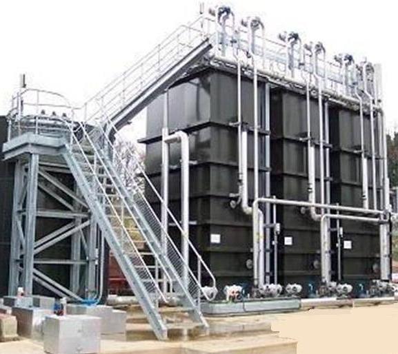
REMOVING OF PHENOL THROUGH INDUSTRYcould be achieved through three beds in series or in parallel, two of them for adsorption and the other for regenerating.(21)
Input Output
Output Input
-6-
Note: (4)
Phenolics concentrations presence differe deponding on type of dying industry either carpets or disperse nylon for example because they rely to pollutant (phenol) loading and percentage of reduction belongs to phenolics
Effect of pH on phenol removal (1)
In any adsorbate-adsorbent system, pH of the system affects the nature of surface charge of the adsorbent, effects ionization and the extent and rate of adsorption. Several 100ml portions of 100mg/l of phenol solution is adjusted to assigned pH with sodium hydroxide or sulfuric acid and were mixed with different adsorbent doses with stirring for 1h.
Advantages
1-It’s considered to be an effective method for the removal of phenol from wastewater because of its large surface area, micro-porous nature, high adsorption capacity
2-The process gives high purity and easy availability
3-It can remove all types of phenols in a simple and easy operation
4-The major advantage is the reduction of heat consumption right at the of this process is regeneration-oxidation step where in a minimal amount of liquid is heated and pressurized.
-7-
Disadvantges
- High cost of activated carbon, its use is sometimes restricted on economical considerations. As such, attempts have been made by different workers to develop alternative adsorbents, preferably of low cost.So we must find another solution more proper for operation with low cost .
2-
(5)
Various chemical processes produse waste water streams which contain phenol.To remove phenol from waste water streams, liquid-liquid extraction is used.
For example with using cumene as extractant,it’s washed with aqueous sodium carbonate and then sodium hydroxide to recover the phenol as phenate.
-8-
IN LIQUID – LQUID EXTRACTION PROCESS we must care about three varaibles during process operation : (6)
1-Operating temperture.
2-Operating pressure.
3-Feed flow rate.
4-PH can play a significant role.
-9-
Flow Sheet Of Removal Of Phenol From Wastewater By Liquid-Liquid Extraction
Advantages: no emulsions, better recoveries, cleaner extracts achievable, the ability to remove many interferences and matrix components selectively . (7)
-10-
Disadvantges : (8)
When to Chose Liquid-Liquid Extraction (9)
• When large volumes of water must be removed to complete a separation. The large latent heat of vaporization of water can make this an energy intensive process.
• When two or more liquids form a close boiling azeotrope, the desired final concentration may not be possible via distillation.
• When one or more of the components are considered thermally sensitive or unstable, distillation may not be a feasible option.
In such cases, extraction is attractive and often preferred. That’s why this process will cost too much ,then we must find another solution !!
-11-
Emulsion Liquid Membranes (ELMs)
It’s an emerging technology depends on the creation of double emulsions.i.e.,water/organic/water (W/O/W) or organic/water/organic (O/W/O) Aqueous sodium hydroxide is used as the internal phase.The caustic reacts with phenol to form sodium phenolate, which is insolube in the organic phase.
Emulsion Liquid Membrane
Operation steps (7)
1-Emulsion is prepared by rigorously mixing the aqueous NaOH solution with the organic phase containing the hydrophobic surfactant.
2-The resulting W/O emulsion is then mixed with the aqueous phenol solution and the W/OW emulsion type liquid membrane is formed.
3-Phenol in the outer aqueous phase diffuses through the liquid membrane of the surfactant containg organic phase and reacts with NaOH upon reaching the inner aqueous phase.The acid –base reaction involved as:
Pheonl is aweak acid and can pass through the organic membrane phase in its undissociated form.Sodium phenolate which is formed in the inner aqueous phase is a strong electrolyte and remains as it respective ions, , and These ions are not soluble in the organic phase and are confined to the inner aqueous phase.Accordingly,phenol can continuously diffuse into the liquid membrane because it disappeare due to the reaction in the aqueous phase.
-12-
Advantages (10)
-Extremely large surface areas generated by the emulsions,resulting in high mass transfer rates.Typical internal-phase mass surface areas are 10^6 m^2/m^3 and external-phase mass transfer areas are in the range of 10^4 m^2/m^3 compared with conventional solvent extraction equipment,ELMs has considerable efficiency.
So we can say finally that ELMs is the best solution for removal of phenol from waste water during dyeing line as it’s so simple and with lower cost from other ways
-13-
Nitrogen Compounds Removal From Wastewater Through Dyeing Line (11)
In determining which method is most suitable for a particular application,the following aspects must be considered :
1-Form and concentration of the nitrogen compounds in the process influent.
2-The required effluent quality of the waste water.
3-Other treatment processes to be applied for removal of other compunds
4-The construction and running costs for process.
5- The reliability of the process.
6-The flexibility of the process.
-Nitrogen in municipal wastewater generally is present as organic nitrogen or ammonia.
The Major Processes In Removal Of Nitrogen
1-Biological nitrification and denitrification
2-Stripping
3-Break-Point Chlorination
4-Ion Exchange
5-Membrane Processss
6-Precipitation
-14-
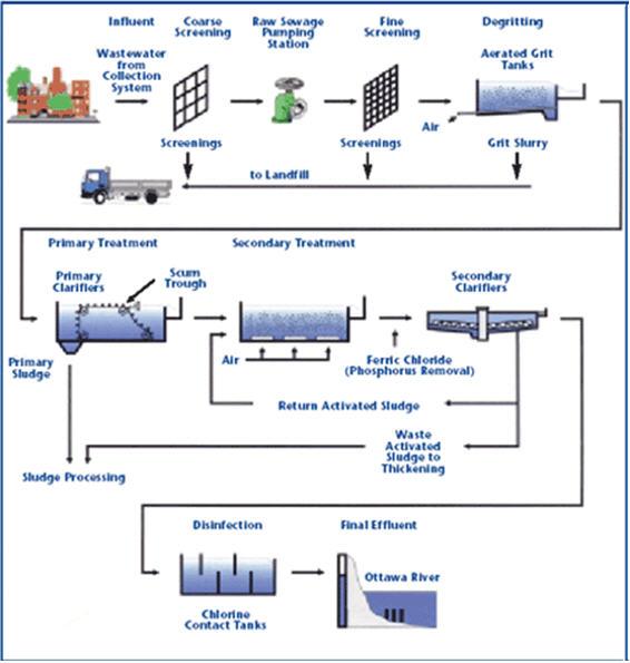
Biotreatment ( Nitrification And Denitrification )
Description Of The Process (12)
-In nitrified waste water the nitrates are converted anaerobically to nitrogen gas the denitrification biological process.Under anaerobic conditions the nitrate serves as the electron acceptor,or hydrogen donor,for the oxidation of organic matter by the faculatative heterotrophic bacteria.This process is restricted to bacteria of the chemoorganotraphic genera.The denitrification process can be carried out in a packed bed or fluidized reactor followed by a clarifier.
-An organic carbon source is needed to act as a hydrogen donor and to act as a carbon source for biological synthesis. Methanol is used as the carbon source because it’s the best for water systems because of its availability,ease of application,and also due to the fact it does not have a residual BOD5 in the effluent
-The detention time required for denitrification of waste water is depending on the nitrate loading and temperture
-The typical wastewater stream contains nitrogeneous compounds (generally present as NH 4 + ) exerting an oxygen demand and measured as BOD 5 and and BOD 20 respectively
-As a result 90% of nitrogen may be removed.
-15-
-16-
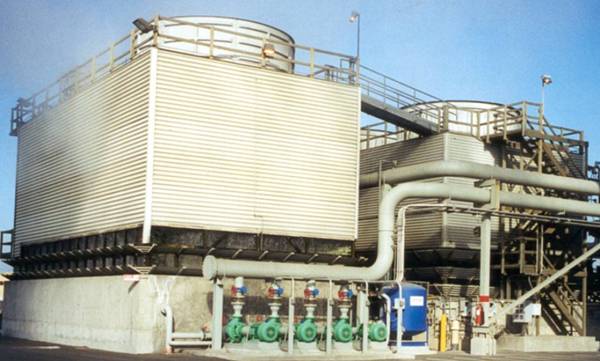
Air stripping
The rate at which ammonia can be removed by air stripping is highly dependent on PH,because the exchange between the two forms,ammonium which is the ion form ,and ammonia , which is ahighly water soluble gas,is an acid base reaction.High efficiency in ammonia removal requires adjustment of PH to about 11.0 prior to the stripping process.
The principal problem associated with ammonia stripping are its inefficiency in cold weather,required shut down during freezing conditions,and the formation of calcium carbonate in the air stripping tower.
The best practical results are achieved by the use of countercurrent packed towers.As the amount of air needed is roughly independent of the ammonia concentrtions,the cost per kg of ammonia removed is much lower at high ammonia concentrtrions.Stripping is ,therfore.most attractive for industrial waste water with ahigh concentration of ammonium
Break-Point Chlorination
It’s accomplished by addition of chlorine to the waste stream in an amount sufficient to oxidize ammonia into nitrogen gas
In practice. Approximately 9-10 mg/l of chlorine is required for every 1 mg/l of ammonia-nitrogen.In addition,the acidity produced by the process must be neutralized.
The chemicals add greatly to the total dissolved solids and result in the substantial operating expenses.
The methods has however, two advantages:
1-By using sufficient chlorine it is possible to obtain effluents reduced in ammonia concentrationto near zero.
2-The low spatial requirement makes it particularly suitable for certain applications disadvantages.
-17-
SO :Which water purification technologies can be applied to remove nitrogen from water?
(13)
After the comparisons between the last ways for removal of nitrogen compounds from waste water during the dyeing industry we will find that the best one is the Break-Point Chlorination because it’s the simplest one during operation and no need for big construction and it’s application is so easy .
-18-
Hydrogen Sulfide Removal From Wastewater Through Dyeing Line
Sulfates play a major role in the production of H2S under anaerobic conditions, or it produces from the reactions producing from the dye itself like when we use the sulfur dyes during the industry.
H2S can cause problems in the environment,especially with regard to odor and corrosion that’s why we had to remove this compounds. (3)
Thus we must find methods to remove this compound from wastewater through dyeing line , those methods like :(14)
1- Chemical Process (Chemical Scrubbers)
2- Removal of Hydrogen Sulfide in Terms of Scrubbing Techniques using Silver Nano-Particles
3-By using of iron salt alone or hydrogen peroxide alone:
-19-
1-Chemical Process (Chemical Scrubbers) (14)
These scrubbers operate by transferring the odorants from the gas phase to the liquid phase.Once in the liquid phase,The odorants are traditionally oxidized or neutralized to allow for additional mass transfer into the scrubbing liquid.
If the odorant can be chemically reacted ,two general chemical processes take place in the scrubbing liquid : acid /base neutralization and chemical oxidation.Acid/base neutralization uses PH adjustments to change the form of the compund.
And this indeed what happen in the removal of hydrogen sulfide.
Hydrogen sulfide is oxidized to form sulfates.Oxidation of hydrogen sulfide is generally not reversible.
To improve the overall efficiency we can use multi-stage scrubbers that are operated in series,it also ,improves the system’s ability to handle load variability and increases operational flexibility .That process can be carried out in one or two stages,thus , that process called commonly sulfide removal.
i.e the use of hypochlorite in the 1st sulfide stage followed by caustic and hypochlorite in the second,or vice versa.
Wet scrubber is used mainly in this process , it’s used with the packed tower and the plate tower being the most common.
But this process have some disadvantages which make it difficult sometimes because :
1- It needs high power requirements .
2- The instruments and construction of scrubber need periodical maintainance to protect them from corrosion that will be caused by the hydrogen sulfide and this maintainance will cost a lot.
3- Water-disposal problems because of settling ponds or sludge clarifiers.
-20-
4- Difficult product recovery : Dewatering and drying of scrubber sludge make recovery of any dust for reuse very expensive and difficult.
.
Packed Bed Tower (15)
That’s why we have to find another solution to remove hydrogen sulfide from wastewater during dyeing industry.
-21-
2-Removal of Hydrogen Sulfide in Terms of Scrubbing Techniques using Silver Nano-Particles: (16)
Silver nano-particles have been used for removal of odorous compounds.
Silver nano-particles in nano sizes (5-30 nm) were prepared on the surface of NaHCO3, the supporting material, using a sputtering method that provided high silver content and minimized conglomerating problems observed in the common AgNO3 photo-deposition method. The silver nano-particles were dispersed by dissolving Ag-NaHCO3 into water, and the dispersed silver nano-particles in the aqueous phase were
applied to remove inorganic odor compounds,H2S , in a scrubbing
reactor. Hydrogen sulfide in the gas phase was rapidly removed by the
silver nano-particles, and the concentration of sulfate (SO4
2-) ion increased with time due to the oxidation reaction by silver as a
catalyst.
Consequently, the experimental results found that this process :
1-Remove s odorous compounds without adding additional energy sources and producing any harmful byproducts
2-It’s effective and economical method for effective removal of odorous hydrogen sulfide
3- Silver (Ag0) or Silver ion (Ag+) has a feature of antibacterial ability and was known as harmlessness to human body .
4-Silver has removal capability for malodorous hydrogen sulfide .
-22-
Experimental:
A.Synthesis of silver nano-particles :
This method has several disadvantages. The first one is disadvantageous on mass production.
Second one is adding dispersing agent because of silver nano particles
condensation.
Accordingly, stirring and sputtering methods for deposition of
silver nano-particles on surface of solid support materials is used.
To synthesis silver nano particles, the stirring rate at 10~30 rpm has been maintained. In order to make particles to nano size, sputtering was stopped before silver formed thin film.
The silver nano-particle aqueous solution is made by dissolving the silver nano particles to attach them on sodium bicarbonate. The concentration of silver nano-particles attached with sodium bicarbonate is1000 mg-Ag/kg-NaHCO3 and silver nano-particles concentration is 50 mg-Ag/L.
B. Batch scrubbing test of silver nano-particle:
Basic operation factors for assessment of silver nano-particle
scrubbing to remove the odorous substance is determined by batch
test. In batch experiment, scrubbing reactor (volume=60L) is made
by the stainless steel tightly filled with the odorous gas at the
consistency. And then aqueous solution of silver nano-particles was
circulated continuously and sprayed out using the nozzle. The volume
of silver nano-particle aqueous solution added in batch reactor is 2L
(58L contaminant gas volume) and the flow of recirculation solution
is 4L/min (2 time circulation per minute).
Silver nano-particle in distilled water, sodium bicarbonate aqueous
solution is used here too.
-23-
C. Continuous scrubbing test of silver nano-particles
The continuous scrubbing reactor used is consisted of stainless steel and has 180 L of total volume. The continuous scrubbing reactor was operated at 90 L/min of gas flow rate corresponding to retention time of 2 minutes. The 4L of silver nano-particle aqueous solution was sprayed out by installation of 4 nozzles on top of reactor. Then the flow rate of silver nano-particle aqueous solution is 6L/min. In order to make silver nano particles to react with odorous compounds effectively, reactor was designed to spray the solution tidy and micro water droplets was made by nozzle.
The tube of inlet and outlet parts was made by teflon to prevent loss of
mass due to adsorption.
-24-
RESULTS
A. silver nano-particle aqueous solution
According to the SEM (Scanning Electron Microscope ) pictures, the diameters of particles are approximately 10~30nm. In order to examine the uniformed distribution of the silver nano-particles in the aqueous solution containing silver particles, TEM (transmission Electron Microscope) and SEM are utilized. From the SEM and TEM analysis, the sizes of particles used in this process are about 5-30nm.
B. Batch scrubbing test of silver nano-particles
-25-
To consider the solubility of hydrogen sulfide and experimental
reproducibility, the initial concentration of hydrogen sulfide is
maintained to 20 ppm in the batch scrubber system.
This figure shows changes of hydrogen sulfide concentration in batch scrubbing system against time. Distilled water was used as control group. After 5minutes, we can't see changes of hydrogen sulfide concentration since equilibrium of hydrogen sulfide between liquid phase and gas phase is made in 5minutes.
In the case of sodium bicarbonate aqueous solution, more hydrogen sulfide is transferred to liquid phase than distilled water because of increased solubility of hydrogen sulfide caused by the increased salt concentrations. In silver nano-particle aqueous solution, most of hydrogen is removed in batch nano-silver reactor. The reason is due to not only increasing of hydrogen sulfide solubility by salt ions in liquid but also oxidizing of hydrogen sulfide ion by silver nano-particles.
C. Continuous scrubbing test of silver nano-particles
To estimate the removal efficiency of hydrogen sulfide here ,
experimental results between sodium bicarbonate aqueous solution and silver nano-particle aqueous solution is compared.
-26-
Change of H2S concentration in the gas phase, and SO4^-2
This figure shows changes of gas phase hydrogen sulfide, and liquid phase hydrogen sulfide and sulfate concentration in batch scrubbing system,respectively.
S^-2 ion concentration in the liquid phase of the continuous nano-silver scrubbing reactor.
At the same influent hydrogen sulfide concentration, changes of
hydrogen sulfide concentration with sodium bicarbonate aqueous solution reached the steady state after 20 minutes. In contrast, with the silver nano-particle aqueous solution, steady state was achieved after 40 minutes. Also, we find that the equilibrium concentration of hydrogen sulfide in silver nano-particle aqueous solution scrubbing system was 6
-27-
ppm. This equilibrium concentration is 3 times less than in sodium bicarbonate aqueous solution scrubbing system showing 17 ppm. The increase of sulfate concentration in liquid phase
indicated oxidation of hydrogen sulfide ion by silver nano-particles in aqueous solution scrubbing system. But sulfate concentration is maintained at a certain concentration in sodium bicarbonate aqueous solution scrubbing system. It showed the reason that hydrogen sulfide ions were oxidized by oxygen free radicals on surface of silver nano-particles. On the other hand, in case of sodium bicarbonate
aqueous solution scrubbing system, some portions of hydrogen sulfide
ions are accumulated in liquid because the oxidation of hydrogen
sulfide ion is not achieved effectively.
As before, because of that two disadvantages these types of this method will make the operation is difficult sometimes.
-28-
3- By using of iron salt alone or hydrogen peroxide alone:
A –By using of iron salt alone:
But we must use a series of iron salt injection to make the process more efficient. At each injection site, the spent iron (FeS) is augmented with fresh iron salt SO we can say that “iron salt” refers to nearly any iron compound and expressly includes iron hydroxide and but excepts FeS, which is often referred here to “spent iron salt”.
The spent iron salt largely remains inert throughout the treatment and disposal processes. When the wastewater reaches the treatment plant, the mass of spent iron salt settles out in the primary clarifiers.
The iron salt demand increases 2-4 fold to achieve H2S emissions control for greater than about four hours hydraulic retention time,thus increasing the amount of spent iron salt generated .The FeS precipitates and constitutes a theoretical solids load of about 3 pounds per pound H2S controlled.The FeS precipitate can cause deposition problems within the system, particularly in low velocity system and claifiers/thickeners as it settles out, thus increasing the actual cost per pound H2S controlled by 20% ($0.075) or more.
H2S controlled is generated when FeCl2 or FeCl3 is used as the iron salt.
-29-
Here the advantages of using iron salt will appeare:
1-Iron salt deplete the alkalinity of the wastewater stream by consuming a minimum of 3 pound calcium carbonate per pound H2S controlled.
2-Iron salt products typically contain 1-4% mineral acid that further depressed the pH of the wastewater.the reduced alkalinity of the wastewater stream in turn reduces the capturing capacity of iron, thus recucing its ability to control H2S to low levels.Then the depressed Ph of the wastewater encourages volatilization of untreated H2S within the wastewater stream.
3- Iron salt deplete the wastewater stream of dissolved oxygen by consuming a minimum of 5 pounds dissolved oxygen per pound H2S controlled.
Note : As iron salts are useful in controlling H2S emissions of wastewater ,it is desirable to minimize the amount of iron salt added to the wastewater stream to minimize the disadvantages associated with the use of iron salts.
B - By use of hydrogen peroxide alone:
The use of hydrogen peroxide H2O2 alone to control H2S emissions is also convential .Like iron salts,H2O2 injection facilities within the system are typically located in series,separated by 1-2 hours hydraulic retention time.
The process occurs through two mechanisms:
(I) Direct oxidation of H2S to elemental sulfur
(II)
Prevention of H2S formation by supplying dissolved oxygen.
-30-
Finally the last method is the simplest proper one and there is no need for huge constructions.
-31-
Removal of cyanide from wastewater during dyeing line
The first step in any waste treatment process is to remove cyanide. Cyanide is used to complex metals such as cadmium, gold, platinum, etc. so that they will remain in solution at high pH ranges.
There are three different methods for removing cyanide. The first, used in Europe but not in the US, is acid hydrolysis. In this process, the pH of the solution is lowered with sulfuric acid and the resulting hydrogen cyanide is captured and recovered. This process is extremely dangerous due to the production of cyanide gas, and is not used in this country.
The second method is to oxidize the cyanide to cyanate with ozone. This method has been demonstrated to work in the laboratory but has not been as successful in the field. The reason for this is most likely due to the short half life of ozone.
The most common method of cyanide destruction is known as alkaline chlorination.
1- Alkaline chlorination.
This is usually accomplished in two stages. In the first stage, the solution pH is raised to approximately 10 - 11. Bleach is added to achieve an ORP(Oxidation-Reduction Potential) level of approximately +500 mv. The solution is then allowed to react for 30 - 60 minutes while the cyanide is oxidized to cyanate. In the second stage, solution pH is lowered to 8.5 - 9.0. Additional bleach is added until the ORP is at a level of approximately +800 mv. This reaction takes 45 - 90 minutes and will oxidize the cyanate to CO2 and nitrogen. At this point the cyanide bearing waste streams can be mixed with the normal non-cyanide bearing waste streams for additional treatment.
It is important to note that cyanide can form complexes that are not amenable to alkaline chlorination. It is therefor important to prevent
-32-
these complex cyanides from forming in the first place. The metals that usually cause these complex cyanides to form are, iron, chrome, and nickel. Once these complexes have formed it may be possible to break them by adding excess bleach and increasing the reaction time.(17)
The disadvantage of chlorination is the cost associated with continuously supplying the source of chlorine to the waste stream which competes with other processes that utilize chlorine. Moreover, the chlorine requirements depend on the cyanide level in the water necessitating close monitoring to make adjustments in the chlorine concentration. Furthermore, the process, requiring refrigeration when recycling the HCN stripper bottoms back to the absorber for the most efficient waste volume reduction, increases the amount of energy and process equipment requirements.(24)
There are another two methods like:
4-By using granular activated carbon
Commercial granular activated carbon (GAC) was used as adsorbent for the adsorptive study of cyanide complexes. The effect of process parameters such as pH, temperature, adsorbent size and dose, contact time on the performance of adsorption is investigated. Optimum pH was found to be 9, 7 and 5 for sodium, zinc and iron cyanides respectively. In the higher temperature range more percentage removal was observed for iron cyanides, whereas, sodium and zinc cyanides were removed optimally at 25–35 °C. Although particle size did not show any major influence on the percentage removal, but optimum size was taken as 2–4 mm. The percentage removal of cyanide compounds increased with the increase in adsorbent (GAC) concentration. However, specific uptake did not increase at GAC concentration above 20–25 g/L. Hence 20 g/L was considered as the optimum dose of adsorbent. Higher removal efficiency
-33-
was achieved for metal cyanides as compared to sodium cyanide at optimal conditions.(18)
BUT high cost of activated carbon restricted on economical considerations and it makes the process need huge constructions.
5-By using precipitation as concentration technology (19)
An improved process for removal of soluble contaminants (cyanide complexes) from wastewater is disclosed which provides significantly enhanced contaminant removal and overall process efficiencies. The improved contaminant removal process is especially suitable for treatment of industrial effluents having high levels of dissolved cyanide. Wastewater undergoes multiple stage sludge treatment, wherein sludge is mixed with wastewater sequentially in a plurality of discrete reaction stages for relatively short retention times. Reaction conditions which promote chemical and/or physical reaction of soluble contaminant with sludge are maintained, and liquid/solids separation is effected after each sludge treatment stage. Oxidizing agent is preferably mixed with the wastewater prior to multiple stage sludge treatment to change the oxidation state of inorganic contaminants and remove cyanide contaminants from solution. Multiple stage sludge treatment may be combined with an improved ferric adsorption process to provide substantially complete removal of inorganic and/or cyanide contaminants.
But this process may need high cost for installation.So we will find that the alkaline chlorination and by using precipitation as concentration technology are the most proper methods for removing cyanide complexes from wastewater during dyeing line .
-34-
Note:
And in general , in removal of pollutants , methods of control like rate of temperature rise , PH , temperature , time differ deponding on fabric type either acrylic or nylon or polyester or cotton (20)
Table Of Content
Introduction 1
Removal of Phenol from wastewater through dyeing line 2
Removal of Nitrogen from wastewater through dyeing line 13
Removal of Hydrogen sulfide from wastewater through dyeing line 18
Removal of Cyanide from wastewater through dyeing line 31
References
1-http://www.altavista.com/web/results?itag=ody&q=removal+of+phenol+in+dyeing+industry&kgs=1&kls=0
2-
http://images.google.com.eg/imgres?imgurl=http://eprints.usm.my/1740/thumbnails/1/preview.png&imgrefurl=http://eprints.usm.my/1740/&usg=__grv7FOiLotdc4xLkbXFoe9F9w6c=&h=302&w=215&sz=118&hl=ar&start=13&sig2=oasXnJz0KIUH9TeZ1rtwqw&um=1&tbnid=irdrh65SKONmgM:&tbnh=116&tbnw=83&prev=/images%3Fq%3Dremoval%2Bof%2Bphenol%2Bby%2Bactivated%2Bcarbon%26hl%3Dar%26um%3D1&ei=-MgnS6XeC9uW_QbzkpGYDQ
to
4-http://www.4shared.com/file/118773673/538e0223/Environmental_problems_in_Dyei.html?s=1
5-http://www.patentstorm.us/patents/pdfs/patent_id/6824687.html
6- http://home.anadolu.edu.tr/~hfgercel/Liquid%20Liquid%20Extraction.pdf
7-http://www.chem.agilent.com/enUS/Support/FAQs/GC/Applications/SPE/Pages/KB000867.aspx
8- http://www.patentstorm.us/patents/6623545.pdf
9- http://www.cheresources.com/liquid_extractor_design.shtml
10-Harry M. Freeman , Industrial Pollution Preventation Handbook, McGraw-Hill, Inc.,New York San ,Francisco, Washington, D.C. ,Auckland ,Bogota ,Caracas, Lisbon ,London ,Madrid ,Mexico City , Milan, Montreal , New Delhi , San Juan ,Singapore , Sydney ,Tokyo ,Toron
11-http://books.google.com.eg/books?id=bjcj7W7PhSgC&printsec=frontcover&dq=removal+of+nitrogen+compunds+from+waste+water&cd=1#v=onepage&q=&f=false
12-Donald R.Rowe,Isma Mohammed Abdel-Magid,Handbook Of Waste Water Reclamation & Reuse.
13- http://www.mhi.co.jp/technology/review/pdf/e424/e424180.pdf
14- http://www.patentstorm.us/patents/pdfs/patent_id/6773604.html
15- http://en.wikipedia.org/wiki/File:Packedtowerex.gif
17- http://www.actglobal.net/products_wastewater_heavy_metals.htm
16- www.waset.org/journals/waset/v59/v59-58.pdf+REMOVAL+OF+H2S+BY+SCRUBBERS&cd=1&hl=ar&ct=clnk&gl=eg" target="_blank" rel="nofollow">http://209.85.129.132/search?q=cache:3MpBxAjn34oJ:www.waset.org/journals/waset/v59/v59-58.pdf+REMOVAL+OF+H2S+BY+SCRUBBERS&cd=1&hl=ar&ct=clnk&gl=eg
17- http://pubs.acs.org/doi/abs/10.1021/i100010a003
18-
http://www.sciencedirect.com/science?_ob=ArticleURL&_udi=B6TFJ-4SWFNXJ-6&_user=10&_rdoc=1&_fmt=&_orig=search&_sort=d&_docanchor=&view=c&_searchStrId=1142313952&_rerunOrigin=google&_acct=C000050221&_version=1&_urlVersion=0&_userid=10&md5=1f294ab319a50e73a1fbce9aa875443d
20- WOODHEAD PUBLISHING IN TEXTILES, ENVIRONMENTAL ASPECTS OF TEXTILES DYEING, EDITED BY R.M. CHRISTIE.
21-http://images.google.com.eg/imgres?imgurl=http://www.amberlyst.com/IMAGE/LEVEL3/brine_process.jpg&imgrefurl=http://www.amberlyst.com/phenol_deacidification.htm&usg=__c60LbPVZpMta-E-qZOHxzYzvA6o=&h=207&w=360&sz=17&hl=ar&start=45&sig2=H-nPdWl_QgsPYaEzmFA4Gg&um=1&tbnid=obdIuAWDld54UM:&tbnh=70&tbnw=121&prev=/images%3Fq%3Dremoval%2Bof%2Bphenol%2Badsorption%26ndsp%3D18%26hl%3Dar%26sa%3DN%26start%3D36%26um%3D1&ei=feQnS7D1EYSO_AbfwaWlDQ
22-W.Lee Kuhre,Seagate Technology,Senior Director Environmental,Health,Safety and Security,University of San Francisco,Graduate Program Senior Lecturer,Practiacl Management of Chemicals and Hazardous Wastes,An Environmental and Safety Professional’s Guide,Prentice Hall PTR,Englewood Cliffs,New Jersy 07632
| |
|


![[MSF+3.jpg]](https://2img.net/h/4.bp.blogspot.com/_SynCnHGx75g/Shl2T3oVhsI/AAAAAAAAAEY/_7oem5pvQ3I/s1600/MSF%2B3.jpg)