مجموعة تكنولاب البهاء جروب
هل تريد التفاعل مع هذه المساهمة؟ كل ما عليك هو إنشاء حساب جديد ببضع خطوات أو تسجيل الدخول للمتابعة.

مجموعة تكنولاب البهاء جروب

تحاليل وتنقية ومعالجة المياه
 
الرئيسيةالبوابةأحدث الصورالتسجيلدخول
تنظيف وتطهير وغسيل واعادة تاهيل الخزانات


معمل تكنولاب البهاء جروب
 للتحاليل الكيميائية والطبية
والتشخيص بالنظائر المشعة
 للمخدرات والهرمونات والسموم
 وتحاليل المياه

مجموعة
تكنولاب البهاء جروب
لتصميم محطات الصرف الصناعى والصحى
لمعالجة مياه الصرف الصناعى والصحى
مجموعة تكنولاب البهاء جروب
المكتب الاستشارى العلمى
دراسات علمية كيميائية


معالجة الغلايات وانظمة البخار المكثف
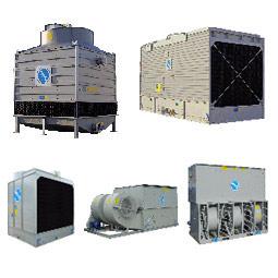
معالجة ابراج التبريد المفتوحة
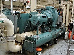
معالجة الشيللرات
مجموعة تكنولاب البهاء جروب
اسنشاريين
كيميائيين/طبيين/بكترولوجيين
عقيد دكتور
بهاء بدر الدين محمود
رئيس مجلس الادارة
استشاريون متخصصون فى مجال تحاليل وتنقية ومعالجة المياه
متخصصون فى تصنيع وتصميم كيماويات
معالجة الصرف الصناعى والصحى
حسب كل مشكلة كل على حدة
تصنيع وتحضير كيماويات معالجة المياه الصناعية
مؤتمرات/اجتماعات/محاضرات/فريق عمل متميز
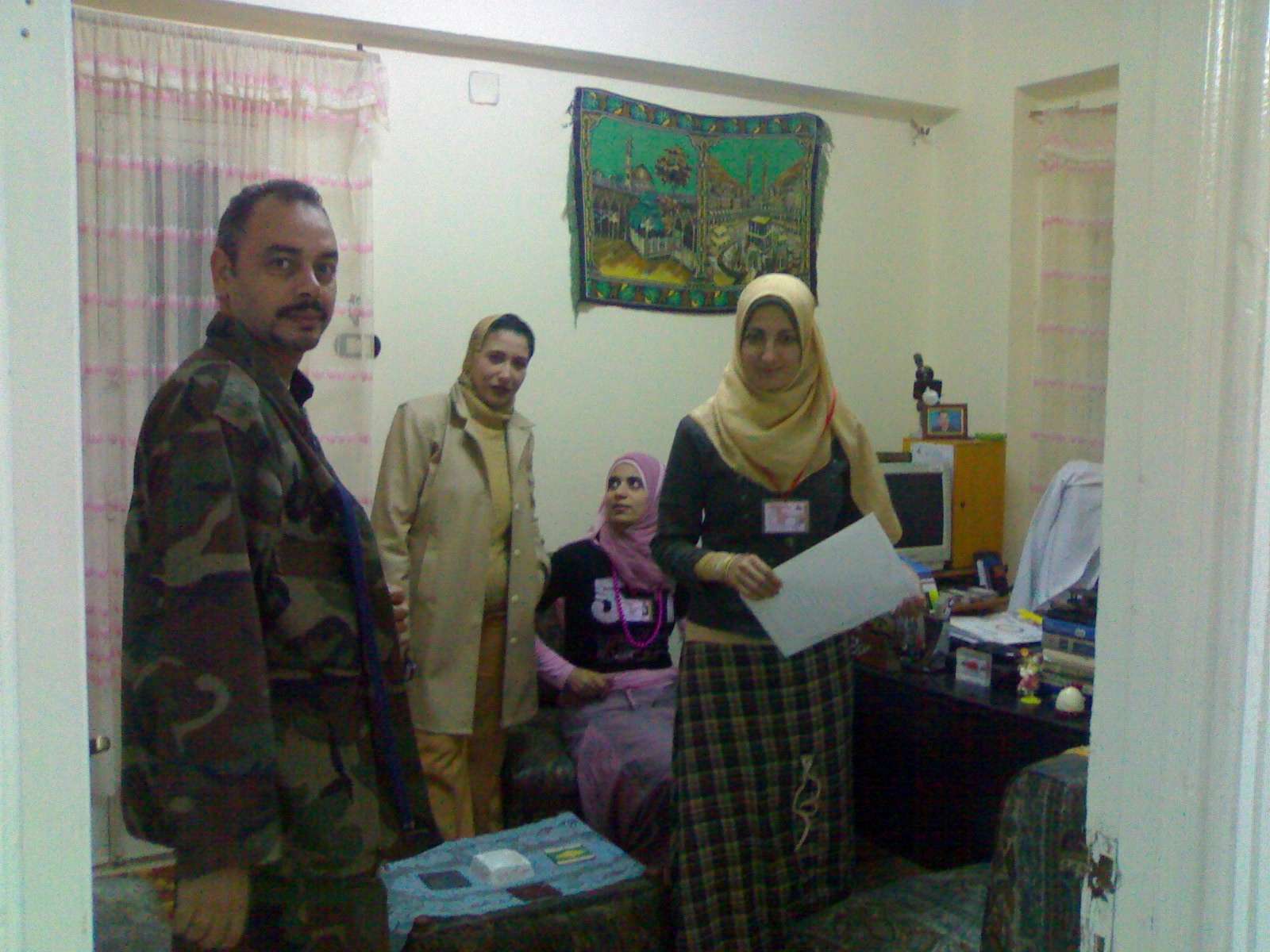
صور من وحدات معالجة المياه


technolab el-bahaa group
TECHNOLAB EL-BAHAA GROUP
EGYPT
FOR
WATER
TREATMENT/PURIFICATION/ANALYSIS
CONSULTANTS
CHEMIST/PHYSICS/MICROBIOLIGIST
 
INDUSTRIAL WATER
WASTE WATER
DRINKING WATER
TANKS CLEANING
 
CHAIRMAN
COLONEL.DR
BAHAA BADR EL-DIN
0117156569
0129834104
0163793775
0174041455


تصميم وانشاء محطات صرف صناعى/waste water treatment plant design

technolab el-bahaa group
egypt
We are a consultants in water treatment with our chemicals as:-
Boiler water treatment chemicals
Condensated steam treatment chemicals
Oxygen scavenger treatment chemicals
Ph-adjustment treatment chemicals
Antiscale treatment chemicals
Anticorrosion treatment chemicals
Open cooling tower treatment chemicals
Chillers treatment chemicals
Waste water treatment chemicals
Drinking water purification chemicals
Swimming pool treatment chemicals
Fuel oil improver(mazote/solar/benzene)
technolab el-bahaa group
egypt
We are consultants in extraction ,analysis and trading the raw materials of mines as:-
Rock phosphate
32%-30%-28%-25%
Kaolin
Quartez-silica
Talcum
Feldspae(potash-sodumic)
Silica sand
Silica fume
Iron oxid ore
Manganese oxid
Cement(42.5%-32.5%)
Ferro manganese
Ferro manganese high carbon


water treatment unit design


وكلاء لشركات تركية وصينية لتوريد وتركيب وصيانة الغلايات وملحقاتها
solo agent for turkish and chinese companies for boiler production/manufacture/maintance


وكلاء لشركات تركية وصينية واوروبية لتصنيع وتركيب وصيانة ابراج التبريد المفتوحة


تصميم وتوريد وتركيب الشيللرات
design/production/maintance
chillers
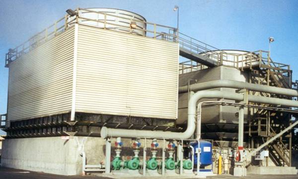
ابراج التبريد المفتوحة
مجموعة تكنولاب البهاء جروب
المكتب الاستشارى العلمى
قطاع توريد خطوط انتاج المصانع
 
نحن طريقك لاختيار افضل خطوط الانتاج لمصنعكم
سابقة خبرتنا فى اختيار خطوط الانتاج لعملاؤنا
 
1)خطوط انتاج العصائر الطبيعية والمحفوظة والمربات
2)خطوط انتاج الزيوت الطبيعية والمحفوظة
3)خطوط انتاج اللبن الطبيعى والمحفوظ والمبستر والمجفف والبودرة
4)خطوط تعليب وتغليف الفاكهة والخضروات
5)خطوط انتاج المواسير البلاستيك والبى فى سى والبولى ايثيلين
6)خطوط انتاج التراى كالسيوم فوسفات والحبر الاسود
7)خطوط انتاج الاسفلت بانواعه
Coolمحطات معالجة الصرف الصناعى والصحى بالطرق البيولوجية والكيميائية
9)محطات معالجة وتنقية مياه الشرب
10)محطات ازالة ملوحة البحار لاستخدامها فى الشرب والرى
11)الغلايات وخطوط انتاج البخار الساخن المكثف
12)الشيللرات وابراج التبريد المفتوحة وخطوط انتاج البخار البارد المكثف
 
للاستعلام
مجموعة تكنولاب البهاء جروب
0117156569
0129834104
0163793775
 
القاهرة-شارع صلاح سالم-عمارات العبور-عمارة 17 ب
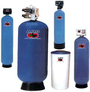
فلا تر رملية/كربونية/زلطيه/حديدية
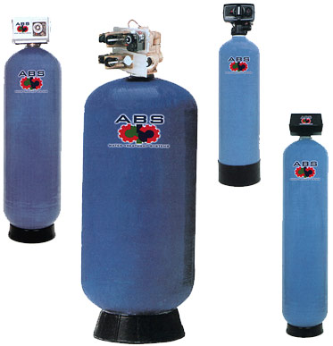
وحدات سوفتنر لازالة عسر المياه
مواصفات مياه الشرب
Drinking water
acceptable
values

50

colour

acceptable

Taste

nil

Odour

6.5-9.2

ph


1 mg/dl

pb

5 mg/dl

as

50 mg/dl

cn

10 mg/dl

cd

0-100mg/dl

hg

8 mg/dl

f

45 mg/dl

N02

1 mg/dl

Fe

5 mg/dl

Mn

5.1 mg/dl

Cu

200 mg/dl

Ca

150 mg/dl

Mg

600 mg/dl

Cl

400 mg/dl

S04

200 mg/dl

Phenol

15 mg/dl

zn


الحدود المسموح به
ا لملوثات الصرف الصناعى
 بعد المعالجة
Acceptable
values
treated wate water
7-9.5

ph

25-37 c

Temp

40 mg/dl

Suspended solid

35 mg/dl

bod

3 mg/dl

Oil & grase

0.1 mg/dl

hg

0.02 mg/dl

cd

0.1 mg/dl

cn

0.5mg/dl

phenol

1.5 ds/m

conductivity

200 mg/dl

na

120 mg/dl

ca

56 mg/dl

mg

30 mg/dl

k

200 mg/dl

cl

150 mg/dl

S02

0.75 mg/dl

Fe

0.2 mg/dl

Zn

0.5 mg/dl

Cu

0.03 mg/dl

Ni

0.09 mg/dl

Cr

0.53 mg/dl

لb

0.15 mg/dl

pb


pipe flocculator+daf
plug flow flocculator
lamella settels

محطات تحلية مياه البحر بطريقة التقطير الومضى على مراحل
MSF+3.jpg (image)
محطات التقطير الومضى لتحلية مياه البحر2[MSF+3.jpg]
some of types of tanks we services
انواع الخزانات التى يتم تنظيفها
ASME Specification Tanks
Fuel Tanks
Storage Tanks
Custom Tanks
Plastic Tanks
Tank Cleaning Equipment
Double Wall Tanks
Septic Tanks
Water Storage Tanks
Fiberglass Reinforced Plastic Tanks
Stainless Steel Tanks
Custom / Septic
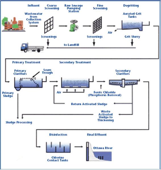
مراحل المعالجة الاولية والثانوية والمتقدمة للصرف الصناعى

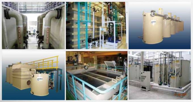
صور مختلفة
من وحدات وخزانات معالجة الصرف الصناعى
 التى تم تصميمها وتركيبها من قبل المجموعة
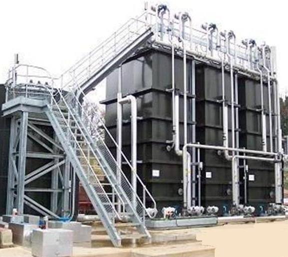
صور
 من خزانات الترسيب الكيميائى والفيزيائى
 لوحدات معالجة الصرف الصناعى
المصممة من قبل المحموعة


technolab el-bahaa group


technolab el-bahaa group


technolab el-bahaa group

technolab el-bahaa group


technolab el-bahaa group


technolab el-bahaa group


technolab el-bahaa group


technolab el-bahaa group


technolab el-bahaa group


technolab el-bahaa group


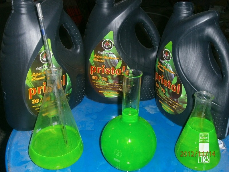
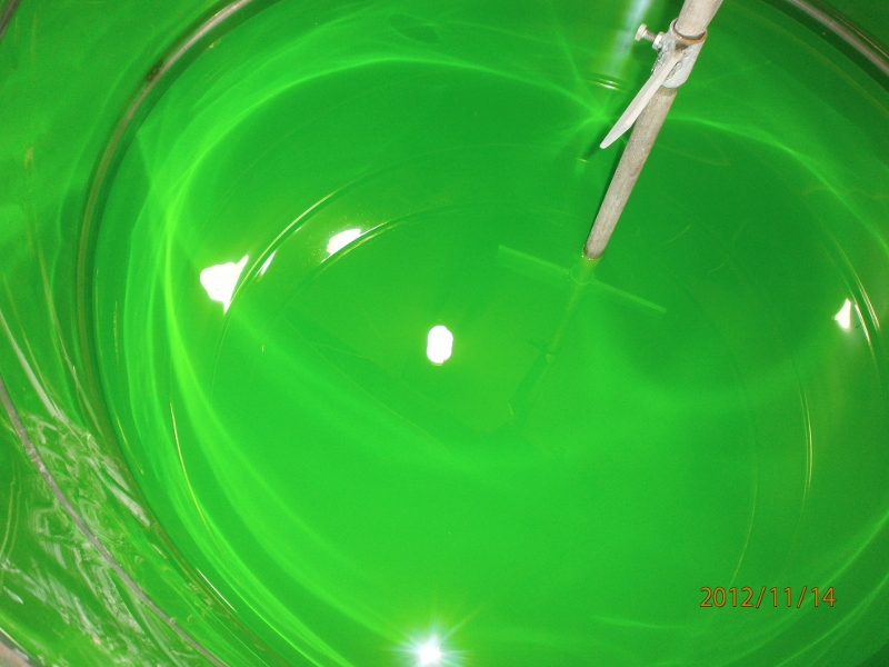
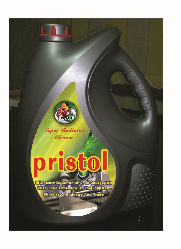
مياه رادياتير اخضر اللون
بريستول تو ايه
انتاج شركة بريستول تو ايه - دمياط الجديدة
مجموعة تكنولاب البهاء جروب
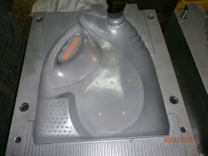
اسطمبات عبوات منتجات شركة بريستول تو ايه-دمياط الجديدة
مياه رادياتير خضراء فوسفورية

من انتاج شركة بريستول تو ايه 

بترخيص من مجموعة تكنولاب البهاء جروب


زيت فرامل وباكم

DOT3


 كيفية تصميم وحدة فصل زيوت بناءا على تحاليل مياه الصرف/ Oil/Water Separator Decision - Flow Diagram

اذهب الى الأسفل 
كاتب الموضوعرسالة
Admin
Admin
Admin


عدد المساهمات : 3762
تاريخ التسجيل : 15/09/2009
العمر : 57
الموقع : مصر

كيفية تصميم وحدة فصل زيوت بناءا على تحاليل مياه الصرف/ Oil/Water Separator Decision - Flow Diagram Empty
مُساهمةموضوع: كيفية تصميم وحدة فصل زيوت بناءا على تحاليل مياه الصرف/ Oil/Water Separator Decision - Flow Diagram   كيفية تصميم وحدة فصل زيوت بناءا على تحاليل مياه الصرف/ Oil/Water Separator Decision - Flow Diagram Emptyالأربعاء فبراير 22, 2012 3:16 am


Oil/Water Separator Decision - Flow Diagram
Determining if your process require an oil water separator or separation SYSTEM

BY
GENERAL.DR
BAHAA BADR

TECHNOLAB EL-BAHAA GROUP

Clarifier Sizing information

Inclined Plate Clarifier Design Parameters

Detailed information on the design and sizing of inclined plate clarifiers and clarification systems

Dissolved Air Flotation SystemDesign & Sizing information

Dissolved Air Flotation Design Parameters

Detailed information on the design and sizing of dissolved air flotation separators and separation systems

Oil Water Separator Design & Sizing information

Oil Water Separator Design Parameters

Detailed information on the design and sizing of oil water separators and separation systems

Misc Info, Data, Spreadsheets & Calculations


EPA Non-Polar Oil Test Methods

Fluid Mechanics

Reynolds Number Calculations

Water Hammer Calculations


HFT Quality Control

HFT Quality Assurance Plan

Steel Fabrications

Leak Test Certification

Interior Coatings

Exterior Coatings

Control Panels

Chemical / Material Compatibility Data

Chemical Pump Dosing Rates

Chemical Compatibility Chart

Properties of Plastic

Coating / Materials Data

Surface Prep Definitions

Standard Internal Coating

Standard External Base Coating

Standard External Top Coating

FRP Resin Cut Sheets

Gel Coat Cut Sheet


STEP 1:

Identify Oily Wastewater Source

Buildings and areas, as well as ALL activities and processes within the buildings and areas, that generate oily wastewater

STEP 2:

Institute Pollution Prevention and Source Elimination / Reduction Procedures
Can the processes that generate the oily wastewater be eliminated?

Can the process be converted to a dry process?


STEP 2-A:

Process altered or eliminated. No further discharge
STOP

No Further Action Required

STEP 3:

Source Diversion

Can the process be moved to an area that has existing oily wastewater treatment equipment in place?

Can the existing separator handle the increased flow?

Is moving the process, diverting the flow economically feasible?


STEP 3-A:

Process relocated or discharge diverted

STOP

No Further Action Required

STEP 4:

Wastewater Compliance Evaluation

Identify permit limits on ALL pollutants generated at the site.

Characterize raw wastewater prior to any treatment if appropriate.

Characterize treated wastewater if existing treatment equipment is in place.

STEP 5:
Discharge & Pretreatment Requirements

Does the raw wastewater meet permit limits and environmental requirements?

Does the treated wastewater meet permit limits and environmental requirements?


STEP 5-A:

Discharge Meets Requirements

STOP

No Further Action Required

STEP 6:

New Separator or System Upgrades Required.

Proceed to Oil Water Separator Design - Flow Diagram

Oil Water Separator Design - Flow Diagram

Basic process in the design of an oil water separator or separation system

STEP 1:

Conduct a Wastewater Characterization Study

The engineer / Designer may conduct wastewater characterization study to establish separator or separation system design parameters.

The first step wastewater characterization study is to conduct the "Test for Determination of Susceptibility of Separation on Oil From Water in a Gravity Type Oil Water Separator".

This bench test will help determine the separators "TARGET" effluent quality at a specific micron removal efficiency.

If possible, you should conduct this test numerous times to allow for variances in your overall process.

STEP 2:

Determine the Type of Separator or Separation System Necessary for Your Process
Evaluate the results of the characterization study and determine the category of oil to be removed.

Decide what type of separator or separation system to use.
The type of oil wastewater separator you need can vary greatly depending on the results of the wastewater characterization study.

API and enhanced gravity separators (parallel plate or "coalescing") are suitable for a great variety of applications.

Emulsion breaking or dissolved air flotation systems may be required for processes with chemically or mechanically stable emulsions.

NOTE:
Hydro-Flo API separators are an excellent separation solution for complex, evolving processes.

Hydro-Flo API separators are designed to evolve with your growing, expanding process requirements.

These robust separators can be retrofit with a variety of DynaPac media and plate packs increasing the efficiency of the separator as your process or discharge requirements change.

Surface drag skimmers, sludge augers, vapor tight lids and even full dissolved air flotation (DAF) system conversions are simple bolt on modifications.

STEP 3:

Do You Have an Existing Oil/Water Separator at Your Facility

If there is an existing oil/water separator on site, evaluate if it may be upgraded to accept the total flow or partial flow from the proposed source to reduce loadings.


STEP 3-A:

Will Upgrading the Existing Separator Bring the Discharge into Compliance
Can the existing system be upgraded by the installation of media (plate packs, coalescing packs, etc.) or adding emulsion breaking capabilities, etc.

STEP 4:

Review Concerns and Requirements of the New Separator or Separation System With the Engineer / Designer

List all provisions that need to be considered to ensure the new system will be accessible for maintenance, will meet site specific area classifications (ie: seismic and explosion proof area classifications, etc.) and will meet all regulatory and effluent discharge requirements.

STEP 3-B:

Can the Existing Separator be Used to Pre-treat the Wastewater Prior to the New Separator

Even if the existing separator is not capable of handling the proposed load, it may be useable as a form of pre-treatment or used in conjunction with the proposed upgrades.


STEP 5:

Write the Specifications for the New or Upgraded Separator or Separation Systems

Write specifications for the new separator, the separator upgrade or the new separation system required to meet all the above listed concerns and requirements.

STEP 3-C:

Incorporate existing separator into design

STEP 3-D:

If determined that the existing separator is no longer suitable for it's current use or unusable in the new system, incorporate the closure of the existing separator into the specifications

STEP 3-E:

Design the upgrade of the existing separator

The Impact of Micron Removal Efficiency on Oil/Water Separator Design

Determining the micron removal efficiency required to meet your effluent requirements (ppm, mg/l) is an important step in the design and sizing on oil water separators.

A small change in the micron removal efficiency can result in a large change in the size of the specified oil water separator.

For example look at the following spreadsheets.


USER INPUTS IN YELLOW

DESIGN FLOW RATE (IN GPM) 150.000


TEMPERATURE (IN DEGREES F) 60.000

SPECIFIC GRAVITY OF THE OIL (IN G/CM³) 0.900

OIL DROPLET SIZE (IN MICRONS) 30.000

MEDIA SPACING ( 0.5 0.75 or 1.20 ) 0.750

MODEL NUMBER 132 - HB - OS - NC - OA

EXAMPLE ONE

USER INPUTS IN YELLOW

DESIGN FLOW RATE (IN GPM) 150.000


TEMPERATURE (IN DEGREES F) 60.000

SPECIFIC GRAVITY OF THE OIL (IN G/CM³) 0.900

OIL DROPLET SIZE (IN MICRONS) 60.000

MEDIA SPACING ( 0.5 0.75 or 1.20 ) 0.750


MODEL NUMBER 39 - HB - OS - NC - OA

EXAMPLE TWO

The only change in the above spreadsheets was the micron removal efficiency "OIL DROPLET SIZE (IN MICRONS)".

All other variables remain the same.

On the first spreadsheet, the "OIL DROPLET SIZE (IN MICRONS)" was input at 30.


On the second spreadsheet, the "OIL DROPLET SIZE (IN MICRONS)" was input at 60.

You will note that the recommended model #'s (which represent the total cubic feet of media required) changed from 132 cubic feet to 39 cubic feet.

That is a 70% change in the total size of the separator.

Both examples are suitable for 150 gallons per minute.

Both examples will remove the target oil with a specific gravity of .90 and less.

The real world difference between the two is that the first example will be far more efficient than the second.

This example should reinforce the importance of accurately conducting the "Wastewater Characterization Study" and the "Test for Determination of Susceptibility of Separation on Oil From Water in a Gravity Type Oil Water Separator".

If you size a separator without knowing the target removal efficiency, you will end up greatly over sizing the separator, because you will need to err on the safe side, and size the separator for maximum efficiency.

Oil/Water Separator "Oil Droplet" Sizes, Definitions and Meanings
Following are the definitions and categories of different oil droplet sizes as defined by the "American Petroleum Institute" in the mid 1970's.

1. FREE OIL: Oil droplets 150 microns in diameter and larger

2. DISPERSED OIL: Oil droplets from 20 to 150 microns in diameter

3. MECHANICALLY EMULSIFIED OIL: Oil droplets less than 20 microns in diameter

4. CHEMICALLY EMULSIFIED OIL: Oil droplets less than 20 microns in diameter with a chemical bond to other molecules

5. STABLE EMULSION/DISSOLVED OIL: Oil in solution with its carrier (i.e. machine cooling solutions)

Solving for and designing a separator capable of removing free oil is relatively easy. Solving for and designing a separator capable of removing dispersed oil is a bit more complicated.

Most manufacturers of oil water separators make the following statement...

The oil/water separator proposed is sized according to the American Petroleum Institutes Publication No. 421 formula for Oil Water Separator sizing.

This separator will remove virtually all free and dispersed oil from the wastewater.

The effluent shall contain less than 10 mg/l of oil droplets greater than 20 microns with a specific gravity of 0.85 or less...

While this statement can be substantiated today by inserting a set of variables into some basic formulas, it is interesting to note that the removal of any oil droplet diameter can be solved mathematically.

But, just because it is calculable does not mean that it will perform that way in the real world.

Even though it is possible to run the calculations for removal of a 20 micron oil droplet, or even smaller,

the conditions have to be perfect to actually achieve it in the real world.

The chart at the right illustrates the comparative difference in the volumes of oil droplets ranging in diameter from 20 to 150 microns.

Below is the conversion from microns to decimals of an inch.

020 micron = 0.000 787 401 574 inch
030 micron = 0.001 181 102 362 inch
040 micron = 0.001 574 803 149 inch
050 micron = 0.001 968 503 937 inch
060 micron = 0.002 362 204 724 inch
070 micron = 0.002 755 905 511 inch
080 micron = 0.003 149 606 299 inch
090 micron = 0.003 543 307 086 inch
100 micron = 0.003 937 007 874 inch
110 micron = 0.004 330 708 661 inch
120 micron = 0.004 724 409 448 inch
130 micron = 0.005 118 110 236 inch
140 micron = 0.005 511 811 023 inch
150 micron = 0.005 905 511 811 inch

Even a 150 micron oil droplet is less than twice the diameter of the typical human hair.
The difficulty in separating oil droplets in the 20 micron range is that their mass is not great enough to overcome the droplet's surface tension.

The droplets bounce off each other like so many marbles, unable to coalesce with other oil droplets or onto the surface of any coalescing media.

Any trace of surfactant or emulsifying agent makes the process even more difficult.

In actual practice, separation of oil droplets down to the 30 to 40 micron range is a realistic goal for any enhanced gravity oil/water separator.


If you do come across someone who says that their separator will "remove 99% of all oil droplets greater than 20 microns" ask them for quantifiable supporting tests to prove the claim.

They will respond with supporting calculations, but no one will respond with any quantifiable study supporting the claims.

Many can supply influent and effluent test results showing the total change across the separator, but no one will be able to supply information on the particle distribution and actual removal efficiencies.


Sizing the Separator or Separation System

Inputting the Accumulated Data to the Hydro-Flo Oil/Water Separator Sizing Spreadsheets to Accurately Size an Oil/Water Separator or Separation System for Your Application

The final step is to insert the data into the appropriate oil/water separator sizing spreadsheet.

• Use the "API Oil Water Separator Sizing Spreadsheet" for API type oil water separators

• Use the "Enhanced Gravity Oil Water Separator Sizing Spreadsheet" for enhanced gravity (DynaPac, MaxiSep, Parallel Plate, Tilted Plate, Corrugated Plate, Coalescing, etc..) type oil water separators.

Comparing and Evaluating Oil/Water Separators and Separation Systems From Different Suppliers

If you go to 10 different oil/water separator manufacturers and ask them to size a separator for a specific application, without giving them a written specification.

For that matter, even when a written specification is supplied, you will get 10 different answers.

Everyone bases the efficiency of their separator on their separator's projected surface area. But, other design variables are all over the map.

Plate spacing will vary from as little as 3/8" to 2", and more.

The angles and configurations of the plates are vastly different from manufacturer to manufacturer.

Overall separator volume from the largest to the smallest designs can fluctuate as much as 150% or more.

When comparing one manufacturer to another, it is best to compare the volume of the separation chamber (or size of the media pack) in cubic feet verses the sell price.

This ratio should give you the separator cost per cubic foot of media.

This is important because the physical size of the separation chamber is the greatest factor in the cost of manufacturing any separator.

The actual projected surface area or "coalescing" area has a much smaller impact on the separators overall cost.

NOTE:

DO NOT COMPARE SEPARATORS BASED SOLELY ON THE AMOUNT OF PROJECTED SURFACE AREA OR COALESCING AREA!

This is VERY important. Many separator manufacturers use the smallest media plate spacing possible in their separators.

This allows them to post the largest projected surface area numbers possible, giving the customer the impression that they are purchasing the most efficient separator available.

If using the smallest possible plate spacing were the answer to building the most efficient separator, we would be building separators with 1/8" plate spacing, or smaller.

Unfortunately, this is not the answer.

Other considerations come into play.

In actual practice, reducing plate spacing to less than 1/2" does not generate improved performance.

Many other issues come into play, such as excessively high cross sectional velocities and Reynolds numbers, plate pack distribution and short circuiting issues, as well as oil and sludge re-entrainment.

الرجوع الى أعلى الصفحة اذهب الى الأسفل
https://technolabelbahaagp.yoo7.com
 
كيفية تصميم وحدة فصل زيوت بناءا على تحاليل مياه الصرف/ Oil/Water Separator Decision - Flow Diagram
الرجوع الى أعلى الصفحة 
صفحة 1 من اصل 1
 مواضيع مماثلة
-
» وحدة فصل الزيوت الخرسانية/CONCRETE OIL/WATER SEPARATOR
» نظريات تصميم وحدات فصل الزيوت عن مياه الصرف المتنوعة/Introduction to Separation of Oil and Water Introduction to Separation of Oil and Water
» كيفية اجراء تحاليل المياه/water quality parameters
» معالجة الصرف الصناعى(كيفية التخلص من السيانيد والفينول من مياه الصرف لمصانع الصباغة والطباعة والتجهيز)
» /نظرية عمل وحدة فصل الزيوت عن مياه الصرف الصناعى

صلاحيات هذا المنتدى:لاتستطيع الرد على المواضيع في هذا المنتدى
مجموعة تكنولاب البهاء جروب :: قسم معالجة وتنقية وتحاليل المياه :: معالجة الصرف الصناعى والصحى-
انتقل الى: