مجموعة تكنولاب البهاء جروب
تحاليل وتنقية ومعالجة المياه
|
تنظيف وتطهير وغسيل واعادة تاهيل الخزانات

معمل تكنولاب البهاء جروب
للتحاليل الكيميائية والطبية
والتشخيص بالنظائر المشعة
للمخدرات والهرمونات والسموم
وتحاليل المياه

مجموعة
تكنولاب البهاء جروب
لتصميم محطات الصرف الصناعى والصحى
لمعالجة مياه الصرف الصناعى والصحى
مجموعة تكنولاب البهاء جروب
المكتب الاستشارى العلمى
دراسات علمية كيميائية
معالجة الغلايات وانظمة البخار المكثف
معالجة ابراج التبريد المفتوحة
معالجة الشيللرات
مجموعة تكنولاب البهاء جروب
اسنشاريين
كيميائيين/طبيين/بكترولوجيين
عقيد دكتور
بهاء بدر الدين محمود
رئيس مجلس الادارة
استشاريون متخصصون فى مجال تحاليل وتنقية ومعالجة المياه
متخصصون فى تصنيع وتصميم كيماويات
معالجة الصرف الصناعى والصحى
حسب كل مشكلة كل على حدة تصنيع وتحضير كيماويات معالجة المياه الصناعية
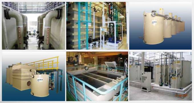
مؤتمرات/اجتماعات/محاضرات/فريق عمل متميز     صور من وحدات معالجة المياه
 technolab el-bahaa group technolab el-bahaa groupTECHNOLAB EL-BAHAA GROUP
EGYPT
FOR
WATER
TREATMENT/PURIFICATION/ANALYSIS
CONSULTANTS
CHEMIST/PHYSICS/MICROBIOLIGIST
INDUSTRIAL WATER
WASTE WATER
DRINKING WATER
TANKS CLEANING
CHAIRMAN
COLONEL.DR
BAHAA BADR EL-DIN
0117156569
0129834104
0163793775
0174041455 تصميم وانشاء محطات صرف صناعى/waste water treatment plant design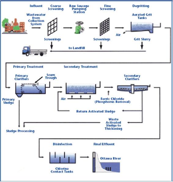 technolab el-bahaa group egypt We are a consultants in water treatment with our chemicals as:- Boiler water treatment chemicals Condensated steam treatment chemicals Oxygen scavenger treatment chemicals Ph-adjustment treatment chemicals Antiscale treatment chemicals Anticorrosion treatment chemicals Open cooling tower treatment chemicals Chillers treatment chemicals Waste water treatment chemicals Drinking water purification chemicals Swimming pool treatment chemicals Fuel oil improver(mazote/solar/benzene) technolab el-bahaa group
egypt
We are consultants in extraction ,analysis and trading the raw materials of mines as:-
Rock phosphate
32%-30%-28%-25%
Kaolin
Quartez-silica
Talcum
Feldspae(potash-sodumic)
Silica sand
Silica fume
Iron oxid ore
Manganese oxid
Cement(42.5%-32.5%)
Ferro manganese
Ferro manganese high carbon technolab el-bahaa group
web sites
e-mails
water treatment unit design 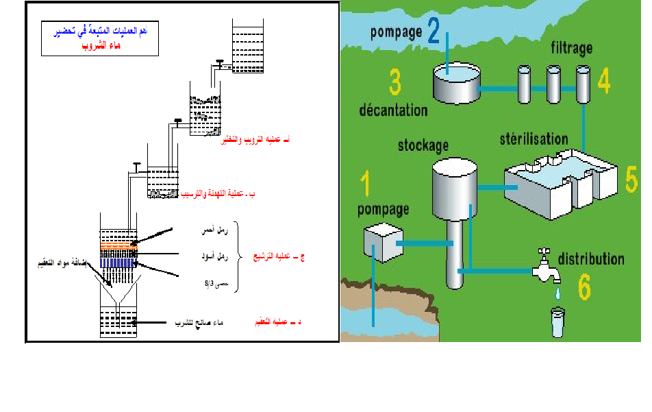
وكلاء لشركات تركية وصينية لتوريد وتركيب وصيانة الغلايات وملحقاتها
solo agent for turkish and chinese companies for boiler production/manufacture/maintance
وكلاء لشركات تركية وصينية واوروبية لتصنيع وتركيب وصيانة ابراج التبريد المفتوحة 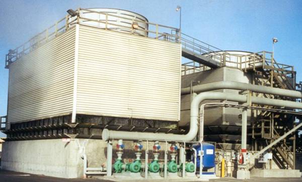
تصميم وتوريد وتركيب الشيللرات
design/production/maintance
chillers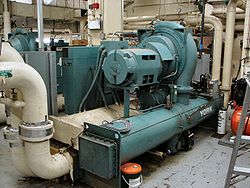 ابراج التبريد المفتوحة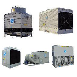 مجموعة تكنولاب البهاء جروب
المكتب الاستشارى العلمى
قطاع توريد خطوط انتاج المصانع
نحن طريقك لاختيار افضل خطوط الانتاج لمصنعكم
سابقة خبرتنا فى اختيار خطوط الانتاج لعملاؤنا
1)خطوط انتاج العصائر الطبيعية والمحفوظة والمربات
2)خطوط انتاج الزيوت الطبيعية والمحفوظة
3)خطوط انتاج اللبن الطبيعى والمحفوظ والمبستر والمجفف والبودرة
4)خطوط تعليب وتغليف الفاكهة والخضروات
5)خطوط انتاج المواسير البلاستيك والبى فى سى والبولى ايثيلين
6)خطوط انتاج التراى كالسيوم فوسفات والحبر الاسود
7)خطوط انتاج الاسفلت بانواعه
 محطات معالجة الصرف الصناعى والصحى بالطرق البيولوجية والكيميائية محطات معالجة الصرف الصناعى والصحى بالطرق البيولوجية والكيميائية9)محطات معالجة وتنقية مياه الشرب
10)محطات ازالة ملوحة البحار لاستخدامها فى الشرب والرى
11)الغلايات وخطوط انتاج البخار الساخن المكثف
12)الشيللرات وابراج التبريد المفتوحة وخطوط انتاج البخار البارد المكثف
للاستعلام
مجموعة تكنولاب البهاء جروب
0117156569
0129834104
0163793775
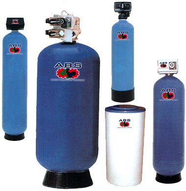
القاهرة-شارع صلاح سالم-عمارات العبور-عمارة 17 ب فلا تر رملية/كربونية/زلطيه/حديدية
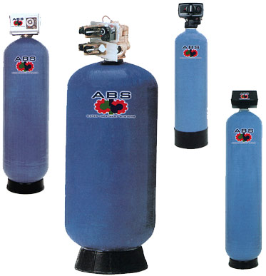
وحدات سوفتنر لازالة عسر المياه
مواصفات مياه الشرب
Drinking water
acceptable
values
50 | colour | acceptable | Taste | nil | Odour | 6.5-9.2 | ph |
1 mg/dl | pb | 5 mg/dl | as | 50 mg/dl | cn | 10 mg/dl | cd | 0-100mg/dl | hg | 8 mg/dl | f | 45 mg/dl | N02 | 1 mg/dl | Fe | 5 mg/dl | Mn | 5.1 mg/dl | Cu | 200 mg/dl | Ca | 150 mg/dl | Mg | 600 mg/dl | Cl | 400 mg/dl | S04 | 200 mg/dl | Phenol | 15 mg/dl | zn |
الحدود المسموح به
ا لملوثات الصرف الصناعى
بعد المعالجة
Acceptable
values
treated wate water
|
7-9.5 | ph | 25-37 c | Temp | 40 mg/dl | Suspended solid | 35 mg/dl | bod | 3 mg/dl | Oil & grase | 0.1 mg/dl | hg | 0.02 mg/dl | cd | 0.1 mg/dl | cn | 0.5mg/dl | phenol | 1.5 ds/m | conductivity | 200 mg/dl | na | 120 mg/dl | ca | 56 mg/dl | mg | 30 mg/dl | k | 200 mg/dl | cl | 150 mg/dl | S02 | 0.75 mg/dl | Fe | 0.2 mg/dl | Zn | 0.5 mg/dl | Cu | 0.03 mg/dl | Ni | 0.09 mg/dl | Cr | 0.53 mg/dl | لb | 0.15 mg/dl | pb |
محطات تحلية مياه البحر بطريقة التقطير الومضى على مراحل MSF+3.jpg (image)محطات التقطير الومضى لتحلية مياه البحر2![[MSF+3.jpg]](https://2img.net/h/4.bp.blogspot.com/_SynCnHGx75g/Shl2T3oVhsI/AAAAAAAAAEY/_7oem5pvQ3I/s1600/MSF%2B3.jpg) some of types of tanks we services
انواع الخزانات التى يتم تنظيفها
ASME Specification Tanks
Fuel Tanks
Storage Tanks
Custom Tanks
Plastic Tanks
Tank Cleaning Equipment
Double Wall Tanks
Septic Tanks
Water Storage Tanks
Fiberglass Reinforced Plastic Tanks
Stainless Steel Tanks
Custom / Septic
مراحل المعالجة الاولية والثانوية والمتقدمة للصرف الصناعى

صور مختلفة
من وحدات وخزانات معالجة الصرف الصناعى
التى تم تصميمها وتركيبها من قبل المجموعة
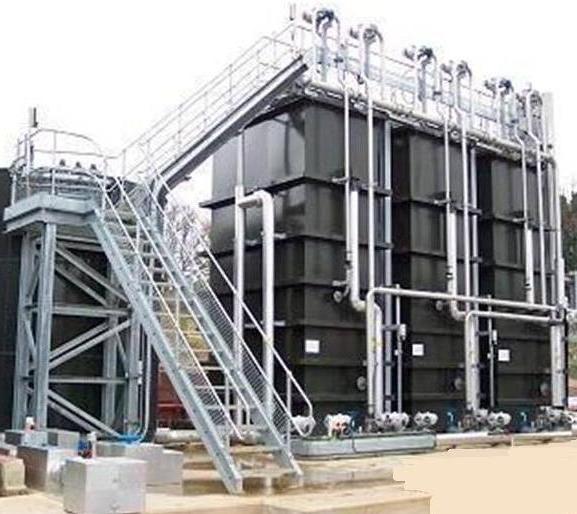
صور
من خزانات الترسيب الكيميائى والفيزيائى
لوحدات معالجة الصرف الصناعى
المصممة من قبل المحموعة
 technolab el-bahaa group
 technolab el-bahaa group technolab el-bahaa group technolab el-bahaa group technolab el-bahaa group technolab el-bahaa group technolab el-bahaa group technolab el-bahaa group technolab el-bahaa group technolab el-bahaa group technolab el-bahaa group technolab el-bahaa group technolab el-bahaa group technolab el-bahaa group technolab el-bahaa group technolab el-bahaa group technolab el-bahaa group technolab el-bahaa group technolab el-bahaa groupمياه رادياتير اخضر اللون
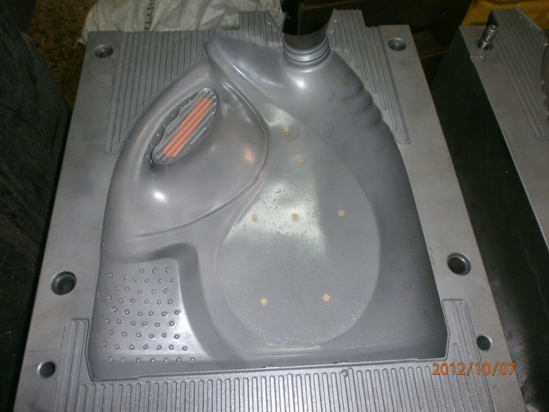
بريستول تو ايه
انتاج شركة بريستول تو ايه - دمياط الجديدة
مجموعة تكنولاب البهاء جروب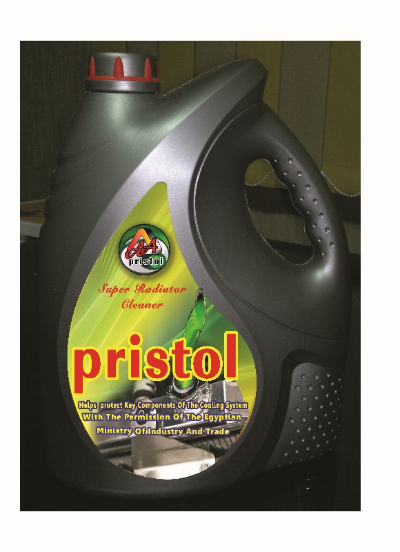
اسطمبات عبوات منتجات شركة بريستول تو ايه-دمياط الجديدة مياه رادياتير خضراء فوسفورية من انتاج شركة بريستول تو ايه بترخيص من مجموعة تكنولاب البهاء جروب 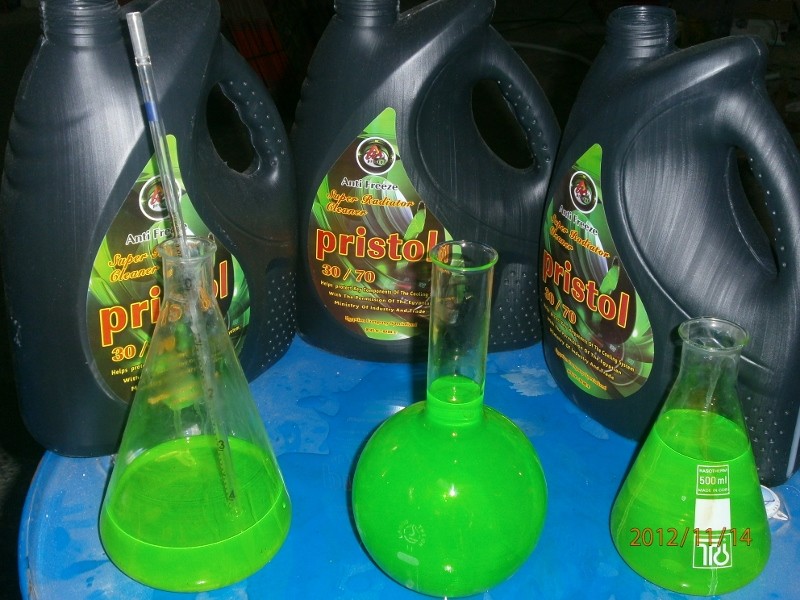

زيت فرامل وباكم DOT3 
|
|
| | نظريات تصميم وحدات فصل الزيوت عن مياه الصرف المتنوعة/Introduction to Separation of Oil and Water Introduction to Separation of Oil and Water |  |
| | | كاتب الموضوع | رسالة |
|---|
Admin
Admin

عدد المساهمات : 3762
تاريخ التسجيل : 15/09/2009
العمر : 57
الموقع : مصر
| موضوع: نظريات تصميم وحدات فصل الزيوت عن مياه الصرف المتنوعة/Introduction to Separation of Oil and Water Introduction to Separation of Oil and Water  الأربعاء فبراير 22, 2012 4:10 am الأربعاء فبراير 22, 2012 4:10 am | |
|
Introduction to Separation of Oil and
Water
BY
GENERAL.DR
BAHAA BADR
TECHNOLAB EL-BAHAA GROUP
Introduction:
Types of separations:
Water from Oil where flow is mostly Oil
Oil from Water where flow is mostly Water
Emulsions
Non-Hydrocarbon oils
Introduction to Theory
Droplets and droplet movement
Stokes’s law
Dissolved vs Non-Dissolved Oil
Water from Oil Separators
Two and three phase separators
Electrostatic Desalters and Treaters
Coalescing cartridge separators
Absorbent separators
Legal aspects
Oil from Water Separators
Pure gravity separators
Spill control separator
API and API Type Separator
Enhanced Gravity Separators
Coalescing plate separators
Inclined plate separators
Horizontal Sinusoidal (flat corrugated) plate separators
Multiple angle separators
“Arc” plate separators
Coalescing tube separators
Packing type separators
Dissolved Air Floatation Systems
Induced Air Flotation Systems
Hydrocyclones and other centrifugal devices
Absorbents
Reverse osmosis and other exotic oil removal systems
Aspects of Selection and Design of Oil Removal Systems
INTRODUCTION:
In refineries, chemical plants, electric power plants and many other industrial facilities the
separation of various oil and water mixtures can cause problems.
These problems are
often the result of imperfect understanding of the nature of the mixtures and how to take
advantage of their properties to accomplish the required separations.
In addition, many states and cities require treatment of stormwater from parking lots and
other facilities where cars and trucks may be present to treat stormwater to ensure the oil
and fuel that may have leaked from the vehicles does not enter the rivers, streams and
lakes.
This course will give an overview of many of the industrial and also stormwater processing
situations that may arise and also some of the means for solving the problems with pros
and cons of many possible designs as well as some suggestions on determining the
nature and extent of the problems and possible solutions.
For purposes of this discussion,
oil means hydrocarbons except where specifically noted otherwise.
TYPES OF SEPARATIONS:
Four main types of separations are likely in industrial plants and numerous more similar
situations exist from time to time. The four most common are:
Water from Oil where main flow is Mostly Oil
Oil from Water where main flow is Mostly Water
Emulsions
Non-Hydrocarbon oils
WATER FROM OIL WHERE MAIN FLOW IS MOSTLY OIL
Separating water from continuous flows of oil is commonly required in oil production
applications, oil refineries and chemical plants as well as some places where it is essential
that the hydrocarbons not be contaminated with water.
The possible problems with water
contamination were first emphasized during the last part of World War II when it was
found that airplanes could fly high enough to cause the water to freeze in the fuel lines.
The pilots found this unreasonably inconvenient because it caused the engines to stop, so
equipment was designed to ensure that only tiny amounts of water were allowed to remain
in the aviation fuel.
It was also found that refinery processes operated easier and better and corrosion
problems were avoided by removing the water from the hydrocarbons.
Numerous types of equipment have been designed to cope with the widely varying
problems of removing the water from the oil and several of these are discussed below.
The problems in removing water from oil vary widely mostly because of the widely varying
viscosity of hydrocarbons that must be treated.
OIL FROM WATER WHERE MAIN FLOW IS MOSTLY WATER
Separating oil from a continuous stream of water is commonly done in oil refineries,
chemical plants, and other industrial facilities for resource recovery as well as
environmental reasons.
It is also practiced in some oil field situations where the flow from
the wells is primarily water.
This design is still
used, but it was not originally designed for environmental purposes and does not generally
produce an effluent suitable for discharge to rivers, streams or lakes.
This method
requires a large residence time and is therefore bulky and costly, so modified design “API
Type” systems are often used.
Since the 1948 study2, numerous designs have been used to remove oil from water and
several are discussed below.
The newer designs make it possible to remove oil from the
water down to less than 10 mg/l.
EMULSIONS:
An emulsion is a mechanical mixture, not a solution, consisting of droplets of one
immiscible fluid dispersed in another continuous fluid.
A good definition, offered by 10, is:
"An emulsion is an apparently homogenous mixture in which one liquid is dispersed as
droplets throughout a second immiscible liquid.
" In the case of water and oil, two types of
emulsion are common, depending on which is the continuous phase.
1. Oil in water emulsions.
2. Water in oil emulsions.
A third type, water in oil in water, is possible but very uncommon.
Emulsions can be very difficult to separate and because of the extreme variations in type,
causes, and treatment are outside the scope of this discussion.
NON-HYDROCARBON OILS
The recent interest in renewable fuels has revived interest in vegetable oils as fuels,
especially as biodiesel.
The vegetable oil and biodiesel systems present different
problems in making the separation between the aqueous and non-aqueous phases.
This
separation is complicated by the relatively high viscosity of most vegetable oils and
solubility issues in biodiesel production facilities.
The systems required for these
separations are substantially different from systems used in conventional hydrocarbon oils
and are outside the scope of this discussion.
Oil and water may relatively conveniently separate using gravity and various enhanced
gravity systems.
In the case of removing oil from water, droplets of oil rise within the
water and in removing water from oil, water droplets fall within the oil.
In cases where the continuous phase is oil, it may be advisable to apply additional force to
help force the water to separate.
In electrostatic desalters and treaters, an electrical field
is applied and in coalescing cartridge separators the use of tightly packed fiber beds are
used.
These situations are discussed in the appropriate sections below; gravity and
enhanced gravity separations are discussed directly following:
Settling of Particles in a Gravity Separator
The settling of solids particles in a clarifier or other settling device, is governed by Stokes's
Law16. This function, simply stated, is:
Where: Vp = droplet settling velocity, cm/sec
G = gravitational constant, 980 cm/sec2
μ = absolute viscosity of continuous fluid, poise
dp = density of particle (droplet), gm/cm3
dc = density of continuous fluid, gm/cm3
D = diameter of particle, cm
Since the equation was developed for solids falling, a particle (or droplet) rise velocity is a
negative number. Assumptions Stokes made in this calculation are:
1) Particles are spherical
2) Particles are the same size
3) Flow is laminar, both horizontally and vertically
x( d - d )xD
(18x )
Vp= G 2
p c μ
From the above equation it may be seen that the most important variables are the
viscosity of the continuous liquid, specific gravity difference between the continuous liquid
and the particle, and the particle size.
After these are known, the settling velocity and
therefore the size of separator required may be calculated.
The velocity of settling or rising is dependent on the hydrodynamic drag exerted on the
settling particle by the continuous fluid.
This drag is dependent on the shape of the particle
as well as the viscosity of the continuous fluid.
This is the same sort of situation that is
found in other cases where a falling object has a high surface area/mass ratio.
In a
vacuum, a feather falls at the same rate as a lead ball. In air or any other resistant media
the ball will fall faster due to the air resistance against the feather.
The same sort of
phenomenon governs the settling of solid particles in a clarifier or other liquid-containing
vessel.
They do not perfectly obey Stokes's Law because of their particle shape.
The pure Stokes's Law calculation depends on knowing the particle size and assuming
that it does not change.
Solid particles flocculate into larger particles of irregular shape
that settle somewhat like snowflakes.
The use of Stokes's Law described above is a very simplified version of the calculations
required for determining clarifier sizing.
More rigorous calculations are required to take
care of such functions as hindered settling.
In considering the rise of oil droplets in water or the fall of water droplets in
oil, it is necessary to consider that the droplets are not a single size, but rather a
continuously changing spectrum of droplet sizes.
For this reason, if it is desired to predict
the performance of a separator the spectrum of droplet sizes must be considered.
Rising of Oil Droplets
Separation of oil and water is different than the settling separation of solids in a clarifier.
Oil droplets coalesce into larger, spherical droplets, while solids agglomerate into larger
masses but do not coalesce into particles that have lower surface/volume ratios like oil.
The rise rate of oil droplets is also governed by Stokes's law. If the droplet size, specific
gravity, and continuous liquid viscosity are known, the rise rate and therefore the required
vessel size may be calculated.
To calculate the size of an empty-vessel gravity separator, it is first necessary to calculate
by the use of Stokes's Law the rise velocity of the oil droplets.
The size of the separator is
then calculated by considering the path of a droplet entering at the bottom of one end of
the separator and exiting from the other end of the separator.
Sufficient volume must be
provided in the separator so that the oil droplet entering the separator at the bottom of the
separator has time to rise to the surface before the water carrying the droplet exits the
opposite end of the separator.
| |
| | | | Admin
Admin
عدد المساهمات : 3762
تاريخ التسجيل : 15/09/2009
العمر : 57
الموقع : مصر
| | موضوع: رد: نظريات تصميم وحدات فصل الزيوت عن مياه الصرف المتنوعة/Introduction to Separation of Oil and Water Introduction to Separation of Oil and Water الأربعاء فبراير 22, 2012 4:28 am | |
| confine ourselves to the examination of oil droplets large enough that the quantity of oil
represented by them may cause environmental problems if discharged into surface or
subsurface waters.
Oil should not be present in quantities great enough to cause oil
sheens or even in the small quantities required to show more than 15 ppm on the
standard EPA tests.
Many jurisdictions, including King County, WA (Seattle)12 have
enacted standards allowing discharge oil levels considerably less than the EPA limit of 15
ppm oil and grease in the water discharged.
In order to minimize the possibility of such
discharge, it is wise to proceed carefully and cautiously in the design of oil-water separator
systems.
NON-DISSOLVED vs. DISSOLVED OILS
In general, all separators deal only with non-dissolved oils.
Most hydrocarbons have very
limited solubility in water, but certain aromatics such as Benzene have substantial
solubility and this must be taken into account in designing equipment where these
chemicals may be present.
If these are present, some other means of removing them
such as distillation may be considered.
WATER FROM OIL SEPARATORS
TWO AND THREE PHASE SEPARATORS
Two and three phase separators are often used in oil production and refining systems and
in chemical plants.
They are usually mostly empty vessels, sized based on empirical
relationships and often provided with rudimentary baffles and / or mesh pads for mist
elimination and heating arrangements to raise the temperature of the oil, thus decreasing
the viscosity and aiding the separation.
Two phase separators may be used where only oil and gas are present with no aqueous
phase or in situations where only small amounts of gas or no gas are present with the
aqueous and hydrocarbon phases.
They are also often known as “free water knockout
drums” and may be designed either as vertical or horizontal vessels. High pressure
systems may be designed as spheres because this is the most economical shape to
manufacture in a high pressure design.
Three phase separators are similar to two phase separators except that they are provided
with connections for water, oil and gas drawoff. Several general designs have been used;
the one shown below is typical of oil field practice.
Three phase separators are commonly
heated as well, with heat being derived from burning some of the gas in the incoming
stream.
ELECTROSTATIC TREATERS AND DESALTERS
The electrostatic desalter / treater process involves the creation of a high voltage electric
field through which the crude must flow from the entrance header below the electrodes to
the exit header in the top of the vessel.
The small water droplets in the crude are
coalesced in the electric field into large droplets which fall rapidly to the interface level
removing entrained salt and speeding up the settling rate of the water phase.
In the unit high voltage is applied to one of two sets of steel Electrode grids in the vessel.
These two sets of grids are parallel to the horizontal center line of the vessel.
The lower
grid (hot grid) is located near the center line of the vessel and is charged with the
secondary voltage or the transformer (high voltage).
This grid is suspended from an
insulated support frame.8
The upper grid is anchored to the vessel wall through the support beam and serves as a
ground grid.
The flow rate determines the required retention time in the electric field.
When this rate is
increased much beyond the capacity of the unit, the coalesced droplets cannot settle out
and some solid particles and/or water may carry over into the product.
Desalters and treaters differ in that desalters usually are provided with additional water
beyond what is naturally entrained in the oil flow and treaters are not.
This is because the
basic function of a treater is to remove the water that is present and the basic function of
the desalter is to remove the salts present by dissolving them in water and removing the
water.
The salts are removed because they cause corrosion problems downstream in the
refinery.
COALESCING CARTRIDGE SEPARATORS
Coalescing Cartridge separators are generally of two types:
• Packed separators, often called “hay packed”
• Filter cartridge separators
Packed Separators:
The packed type separators were first developed at the end of World War II for treatment
of aviation gasoline to remove water.
The term “hay pack” is really misleading because
the material often used is excelsior (shredded wood) and not hay.
The media is a densely
packed bale of fibrous material such as the excelsior, stainless shavings, Teflon shavings
or other fibrous material.
These systems generally include one or more bales of media in a horizontal pressure
vessel and operate by providing a surface for the aqueous phase to accumulate on and by
causing generally laminar flow to allow some settling time without channeling.
The
hydrocarbons flow horizontally through the vessel and as this is occurring, the aqueous
phase accumulates on and in the packs and forms large droplets which drain down to the
bottom of the vessel and are removed there.
Coalescing “Hay Pack” constructed of excelsior wood shavings.
(Note: Shown placed on end: support wheel on end would be vertical when installed)
While excelsior type products are effective to a degree in achieving the desired results
some problems and limitations are encountered.
Excelsior has a limited life span in that,
being organic, it will decompose.
Excelsior, or any equivalent natural or synthetic fibrous
type material, has a tendency to clog easily with dirt, debris, and other contamination so
that, in many instances, frequent replacement is required.
The results of clogging due to
collection of debris and contaminants tends to cause the fluid to channel, that is, the fluid
flows through the filter media in small channels so that only a relatively small percent of
the filter medium is actually effectively utilized.
Another difficulty with the use of excelsior
and similar configured natural and synthetic materials is that such materials are, by their
nature, randomly oriented, having no preferential direction of inclination of elongated
components.
For this reason water droplets coalescing on such material are not
preferentially downwardly oriented in their flow path, and therefore droplets can detach
from horizontal portions of the filter medium and become resuspended in the fluid stream.
FILTER CARTRIDGE SEPARATORS:
Filter cartridge type separators are often used in treating refined petroleum products to
remove water generated as part of the processing or acquired during time in pipelines or
tankage.
The cartridges used are generally composed of a dense fiberglass mat held
together with a phenolic plastic binder and are used in conjunction with a screen separator
cartridge of a hydrophobic nature.
The flow is commonly from inside to outside in the
coalescing cartridge and outside to inside in the separator cartridge.
The water drops are
coalesced into large drops in the coalescer cartridge and are barred from exiting the filter
vessel with the hydrocarbons by the separator cartridge.
Because the coalescer
cartridges are very dense they are also fine filter cartridges and tend to plug easily (much
more easily than the packing described above or other methods of separation).
For this
reason they are only used where excellent water removal is necessary and few or no solid
particles are present.
Common applications are treating jet fuel, gasoline, or kerosene for
water removal. Figure 4 below shows a schematic of the operation of a typical coalescer
/ separator system.
ABSORBENT SEPARATORS
Absorbents are often used as a final treatment stage in the use of hydrocarbons such as
jet fuel or gasoline.
Referring to them as “separators” is a misnomer because they do not
separate and remove the water they only sequester it so that it cannot pass downstream
to the automobile or airplane.
They are compact and easily mounted on a fueling truck,
but are a very expensive way to remove water from hydrocarbons and are only used
where absolutely necessary.
Legal Aspects
In general, water is only removed from oil and other hydrocarbons in an industrial setting
and there is limited or no discharge to the environment, so the only legal aspects of
treating oil to remove water are the safety aspects (OSHA, etc.) and possible legal
aspects of discharge of the water.
For this reason, the following only deals with the legal
aspects of removing oil from water.
Oil in water discharges from industrial and other facilities are governed by a variety of
federal, state and local laws.
Included are the Clean Water Act (CWA) and its
amendments, the Oil Pollution Act of 1990, the Coastal Zone Management Act and others
5.
Most hydrocarbon wastes are not covered by the Resource Conservation and Recovery
Act of 1976 and its amendments (RCRA) or the Comprehensive Environmental Response,
Compensation, and Liability Act (CERCLA) also known as the Superfund Act5.
These
wastes, produced by the extraction, transportation, refining, or processing of oil and
natural gas, are specifically exempted from being regulated as "hazardous wastes" under
any other laws.
The basic law covering discharges is the Clean Water Act.
It was originally enacted as the
Federal Water Pollution Control Act of 1972, but was amended extensively in 1977.
The
1977 amendments, in conjunction with the earlier legislation, became known as the Clean
Water Act. Under the terms of this Act, amended Section 402 created the National
Pollutant Discharge Elimination System (NPDES) permit system.
Permits for point sources
under this system are granted by the Environmental Protection Agency (EPA) or by states
with EPA approved programs.
After enactment of this law, any discharges other than
those covered by the permit are illegal.
Although the Clean Water Act was enacted
primarily to control discharges from Publicly Owned Treatment Works (Sanitary Sewer
Plants) and toxic discharges from industrial plants, it also controls discharges of petroleum
and other hydrocarbons into the waters of the United States.
Most states and localities require discharges to contain 15 ppm or less oil and grease,
based on a 24 hour composite sample.
Oil and grease may include petroleum
hydrocarbons as well as animal and vegetable oils. Some localities have established
lower discharge limits. King County, Washington, which includes the Seattle area, requires
discharges to be less than 10 ppm12.
Also important are the new stormwater management rules published by the EPA in 1990
(NPDES Permit Application Regulations for Storm Water Discharges; Final Rule, 1990).
The reasoning behind stringent regulation of stormwater is included in the "National Water
Quality Inventory, 1988 Report to Congress", as discussed in the Federal Register,
November 16, 1990.
This report concludes that "pollution from diffuse sources, such as
runoff from agricultural, urban areas, construction sites, land disposal, and resource
extraction is cited by the States as the leading cause of water quality impairment.
" These
sources appear to gain in importance as discharges of industrial process wastewaters and
municipal sewage plants come under increased control.
Stormwater discharges were covered under the CWA but not required to have permits
under the NPDES system until the final rules were published in the Federal Register,
November 16, 1990. "Stormwater discharges" refer to discharges consisting entirely of
rainwater runoff, snowmelt runoff, or surface runoff and drainage. Waters that do not meet
this definition are not covered by these regulations.
The new rules specify that facilities
with stormwater discharges from "areas containing raw materials, intermediate products,
finished products, by-product, or waste product located on site" will require a NPDES
permit.
Several categories of facility are specifically exempt from these regulations,
notably stormwater runoff from mining operations, oil and gas exploration, production,
processing, or treatment operations, and parking lots whose rainwater sewers are not
interconnected with manufacturing facility sewers.
It should be noted that the above concerns mostly legal aspects of discharging waters
directly to rivers and streams.
If it is desired to discharge the water to a sanitary sewer,
different rules apply:
DISCHARGE TO SANITARY SEWER (PRETREATMENT)
Sanitary sewer authorities are under the same requirements as other dischargers to the
waters of the US:
They must meet the requirements of the Clean Water Act. In addition,
these authorities must also meet the requirement of the Clean Air Act (industrial
dischargers do too, but their discharges to air are not directly tied to the water quality as
are the sanitary sewer plants).
To meet their air discharge permit requirements, most
sanitary sewer authorities require industrial discharge to the sanitary sewer to have a
maximum oil content.
The allowable amounts vary, but are often about 100 mg/l oil in the
water.
Many industrial plants choose to discharge their wastewater to sanitary sewer because
the regulatory paperwork requirements are less.
If it is desired to make such a discharge,
the local authorities must be consulted to determine their requirements for discharge
quality and monitoring. Technical solutions to problems with discharge to sanitary sewer
are much the same as solutions to discharge to surface water, but may be easier to
implement because of (usually) higher discharge limits.
SYSTEMS AVAILABLE FOR REMOVING OIL FROM WATER
Systems for removing oil from water range from very simple holding ponds with or without
skimming arrangements to very elaborate membrane technology-based systems.
For
most applications in removing oil, the simplest systems are often inadequate (although
often used) and the most complicated are either too expensive or too maintenance intensive.
Most of the following discussion, therefore, will concentrate on methods of
separation intended to meet regulatory requirements with minimum cost and maintenance.
Gravity Separation
The simplest possible separator is an empty chamber with enough volume to contain
spills. A typical spill control separator i.
A spill control separator is too
small to intercept small droplets and is only suitable for intercepting spills of oil or grease.
Spill control separators are only effective if any accumulated oil is removed regularly.
If the
oil is not removed regularly, a storm may flush the accumulated oil out of the separator
into the downstream sewer.
API separators are gravity type separators similar to spill control separators, but are
generally larger, more sophisticated, more effective, and are usually equipped with oil
removal facilities.
The American Petroleum Institute (API) provides design criteria for oilwater
separators. A design method is provided in the API Manual on Disposal of Refinery
Wastes,
1.
API separators are extensively used in oil refineries and chemical processing facilities
where waters containing relatively large amounts of oil are present and need to be
processed to meet the requirements of NPDES permits.
A diagram of a typical API
separator is shown in Figure 6 (Adapted from API Publication 421, 1990).
It should be
noted that this same API publication contains a survey of refinery API separators that
indicate most of them do not meet the requirements of the Clean Water Act.
The API separator has successfully been used in refineries for many years.
It is much
more effective than simple holding ponds or spill control separators.
Advantages of the
spill control separator and API separator are simplicity of design, low cost, low
maintenance, and resistance to plugging with solids.
The primary disadvantage of these
simple gravity separators is the poor quality of separation that they provide.
It should also be noted that the design method for API separators mentioned above
requires approximately a 45 minute residence time and many separators which are
utilized as “API type” do not include enough volume to provide the 45 minutes residence
time required. | |
| | | | Admin
Admin
عدد المساهمات : 3762
تاريخ التسجيل : 15/09/2009
العمر : 57
الموقع : مصر
| | موضوع: رد: نظريات تصميم وحدات فصل الزيوت عن مياه الصرف المتنوعة/Introduction to Separation of Oil and Water Introduction to Separation of Oil and Water الأربعاء فبراير 22, 2012 4:48 am | |
| Enhanced Gravity Separation
Enhanced gravity separators provide better separation quality than is possible with simple
gravity separators while maintaining the low capital and maintenance cost benefits of the
simple systems.
In many ways, the enhanced gravity separators substitute sophisticated
design for the settling time provided in pure gravity separators.
These enhanced gravity
separation systems have some similarity to API separators, but include additional internal
features that enhance the separation of oil and water.
These internal features are basically
a substitute for the additional residence time provided by the API separators.
Designs that have successfully been used are:
1) Coalescing plate separators
a. Inclined plate separators
b. Horizontal Sinusoidal (flat corrugated) plate separators
c. Multiple angle separators
2) Coalescing tube separators
3) Packing type separators
Coalescing plate separators:
Inclined plate separators
Inclined plate separators have been used successfully for many years. These systems are
usually made in large modules constructed of fiberglass corrugated plates packaged in
steel or stainless steel frames.
The oil droplets entering the system rise until they reach
the plate above, then migrate along the plate until they reach the surface.
Plates in this
type system are often 3/4" apart, but may be as much as 4" apart.
These separators are
also known as CPI (corrugated plate interceptor) separators.
Advantages of this system include improved efficiency at removing both solids and oil
(over API type separators) and resistance to plugging with solids.
schematic of a typical inclined plate separator.
Separators of this general type may be configured in several orientations, with the flow
perpendicular to the plates as shown below, parallel to the plates in upflow manner and
parallel to the plates in downflow manner.
The design varies with the manufacturer and
exact service required.
Flat Corrugated (Horizontal Sinusoidal) Plate Separators
Flat corrugated plate separators often use horizontal oleophilic polypropylene plates
stacked one on top of another in vertical stacks and fastened into packs with rods or
wires.
The system uses a combination of laminar flow coalescence and oleophilic attraction.
Slowing the flow of water to low velocities where laminar flow regimes exist minimizes
turbulence.
Turbulence causes mixing of the oil and water and reduces oil droplet sizes.
Stokes's law states that larger droplets will rise faster and thus separate better.
The
oleophilic nature of the plates allows the oil droplets to attach and encourages them to
coalesce into larger ones which will rise faster.
These plates provide better separation than could be arrived at without plates.
The
advantages of this system are that the plate packs are modular and relatively small in size
compared to the inclined plate modules.
Corrugated plates in this type system are spaced
a nominal 0.25" to 0.5" apart. Because the plates are corrugated, rise distances of
droplets in the vertical direction are greater than the perpendicular distance between
plates. The oil droplets must rise approximately 0.4" for the nominal 0.25" spacing and
0.7" for the nominal 0.5" spacing.
Because spacing varies slightly due to variations in plate
molding and assembly the spacings are referred to as nominal 0.25" and 0.511 while
varying somewhat from these dimensions.
Because the vertical rise distance
to be covered is less than for the inclined plate systems, the same size particle is
separated in less time.
Conversely, the same amount of space time provided within the
plate area causes effective separation of smaller size particles.
Disadvantages of this system are possible plugging of the plate packs by solids and
possible damage to the plates by solvents that could attack the polypropylene plates.
Plates placed vertically help to alleviate plugging by solids, but do not coalesce as
effectively.
Multiple Angle Plate Separators
Multiple angle plate separators were developed to take advantage of the virtues of the
horizontal sinusoidal separator plates while eliminating many of the disadvantages.
The
plates are corrugated in both directions, making a sort of "egg-carton" shape. Spacers are
built into the plates for two spacings (nominal 0.25" and 0.5", or 8 mm and 16 mm).
Advantages of the multiple-angle system are:
The plates are designed to shed solids to the bottom of the separator, avoiding plugging
and directing the solids to a solids collection area.
In inclined plate systems, solids must
slide down the entire length of the plates whereas in the multiple angle systems the solids
only have to slide a few inches before encountering one of a multitude of solids removal
holes.
The solids drop directly to the bottom of the separator.
The double corrugations provide surfaces that slope at least a forty-five (45) degree angle
in all directions so that coalesced oil can migrate upward.
The holes in the plates that
constitute the oil rise paths and solids removal paths also provide convenient orifices for
insertion of cleaning wands.
The advantages of the aboveground units are that they are factory fabricated and require
a minimum of field installation time.
Most large units are designed utilizing plates installed
in in-ground vaults.
The primary advantages of vault installations are that the cost per unit
flow is minimized and the below-grade installation is both convenient for gravity flow
applications and does not waste valuable plant area.
A typical large underground vault system utilizing multiple angle plates is shown below
during installation at a facility in Canada.
ARC PLATES
A compromise between flat corrugated and multiple angle plates, “arc” plates are often
used in stormwater processing and industrial applications.
Their operation is very similar
to both the horizontal plates and multiple angle plates.
Coalescing tube separators:
Coalescing tube separators utilizing perforated plastic tubes for separation have been
used for separation of oil and water.
The advantages of the use of this type separator are
low cost and enhanced separation due to the oleophilic nature of the packing.
The
disadvantage is that the oil separation from the tubes is more or less random and
therefore not optimized.
These separators are usually made with the tubes in the vertical
position but some are constructed with the tubes horizontal. Operation of the two designs
is substantially the same.
Packing type separators:
One other system that can be used for coalescence is routing the emulsion through a bed
of packing10.
Experimental data indicates that most of the coalescence occurs in the first
few inches of excelsior.
This type of coalescer is often used in conjunction with gravity
separation or inclined plate separation as a polishing stage.
Similar packs have been
made of other materials, including stainless steel and polypropylene.
Systems of this type
can be efficient, but the tightly packed coalescing media can experience plugging
problems.
Coalescing media of this type is often used as a second stage after a plate type
first stage of separation. In this type application, it is common to use plastic woven mesh
of the type often used as demister pads in distillation columns.
DISSOLVED AIR FLOTATION (DAF) SYSTEMS
Another treatment device for oil removal is the conventional dissolved air flotation (DAF)
system.
In the DAF process, a portion of the effluent from the DAF is pressurized and air
is injected into the recycle stream.
The air-laden recycle stream passes through a
backpressure valve and then is mixed with the raw influent. Once the pressure is released
on the recycle stream, the air comes out of solution in the form of tiny bubbles, many in
the range of 40-80 microns.
These tiny bubbles attach themselves to particulate matter in
the wastewater and the buoyant force on the combined particle and air bubbles is great
enough to cause the particle to rise to the surface.
In this way most oil droplets in the
stream are captured.
While these systems are very effective at removing oil and particulates, they are very
expensive compared to gravity systems, both in capital costs and operating / maintenance
costs.
INDUCED AIR FLOATATION SYSTEMS:
Induced Air Flotation (IAF) systems are similar to DAF systems in operation except they
use induced air instead of air this dissolved and allowed to come out of solution.
A typical IAF unit would include a pump-like device mounted vertically in a tank with the
motor above the water and the diffuser disc below.
The diffuser disc incorporates fine
holes near its perimeter for ultra-fine bubble diffusion into the liquid.
The motor turns the
diffuser disc at a high speed, creating a low-pressure zone at the disc’s diffuser ports,
which draws air, or gas, from above the liquid surface.
That air, or gas, then proceeds
down through the draft tube, into the disc and out of the submerged diffuser ports. Each
bubble exits through a hole in the edge of the diffuser disc.
The spinning disc shears it into
microscopic air bubbles measuring from 10-100 microns in diameter.
These air bubbles
adhere to minute solids such as oil and grease.
The bubbles slowly rise to the surface
around the unit, bringing the solids to the surface.
These units have the same general advantages and disadvantages as DAF systems but
are somewhat less complicated.
EXOTIC SYSTEMS:
Reverse osmosis membranes and other exotic means of removing oil from water are
sometimes used.
These units are usually too expensive to be used for wastewater
treatment.
HYDROCYCLONES AND OTHER CENTRIFUGAL DEVICES
Hydrocyclones are used in situations where there are extremely high solids loadings that
would plug other equipment or where there is a high pressure water stream that needs to
be at a lower pressure.
They have high operating costs if there is not a free pressure drop
available because they require a lot of energy input to operate.
They are also flow rate
sensitive and do not operate well at much below 90% of the design flow rate.
Other centrifugal devices (usually called “swirl” devices) have been offered as stormwater
processing equipment.
These evidently remove some grit and other debris, but do not do
much to remove oil.
Testing on one such system in the UK11 indicated an effluent of about
60 mg/l of oil which would not meet the requirements of the US Clean Water Act.
ABSORBENT SYSTEMS:
Another expensive but effective means of removing residual oil in water is the use of
activated carbon or other absorbents such as polyester or polypropylene fibers, sawdust,
and .
Carbon is sometimes used as a polishing step, but can be prohibitively expensive if
the first stages are not effective.
The advantage of the use of absorbents is that it is possible with their use to get to nondetectable
levels of hydrocarbons in the effluent water.
In addition, no other equipment is
usually needed – absorbents are simply thrown on the water to absorb the hydrocarbons.
The problems with their use are that, on a per pound of hydrocarbon removed from the
water, they are very expensive and because they are readily used up, they are usually not
changed frequently enough.
The result can be that there is no system at all to remove the
oil from the water.
SELECTION AND DESIGN OF OIL-WATER SEPARATOR SYSTEMS
General Design Considerations
Numerous factors must be considered in the selection and design of oil-water separation
systems. Among these are:
1. Flow rate and conditions
2. Degree of separation required - effluent quality
3. Amount of oil in the water
4. Existing equipment
5. Emulsification of the oil
6. Treated water facilities
7. Recovered oil disposal method
For industrial and some municipal applications, flow rate, amount of oil, flowing
temperature, and other conditions affecting separation such as whether flow is laminar or
turbulent may be easily determined.
The degree of separation required is usually a matter
of statutory or regulatory requirements, but if the water is discharged to a sanitary sewer
plant or industrial treatment plant it may be negotiable.
The amount of oil in the water may be known, especially in industrial applications, but it
will often be necessary to estimate the quantity in stormwater applications.
Equipment
manufacturers can provide guidance about quantities to be expected, and some
information has been published about stormwater quality 7,6, 17, and 15.
Existing equipment such as API separators may affect the design of equipment to be
used. Often it is possible to retrofit existing equipment with more sophisticated internals to
enhance separation quality.
The degree of emulsification of the oil is difficult to assess, but
steps can be taken to discourage the formation of emulsions and encourage the breakup
of emulsions that are inadvertently created.
It may be necessary to substitute quick-break
detergents for conventional detergents that are also emulsion causing. Quick-break
detergents are those detergents designed to remove the oil (or grease) from the item to be
cleaned and then quickly dissociate again from the oil, leaving the oil as free hydrocarbon
droplets in the water.
It is necessary to ensure that adequate size piping is provided for downstream treated
water removal to avoid flooding the separator and perhaps filling the oil reservoir with
water.
A downstream test point should be provided to allow for effluent testing. Adequate
storage facilities for the removed oil should be provided and means for recycling the oil
included.
Careful records of removed and recycled oil should be kept to avoid possible
future regulatory problems.
The following is a discussion of several of the points touched briefly on above concerning
design of oil-water separation systems.
Influent Conditions
Much of the performance of an oil-water separator depends on the influent conditions.
Because smaller droplets are more difficult to separate, equipment or conditions that form
small droplets in the influent to the oil-water separator will cause the separator to be
designed larger to accommodate the additional time required for the smaller droplets to
coalesce.
Conditions that form small droplets are any conditions that cause shear in the
incoming water. The following are (more or less in order of severity) some factors that can
cause small droplet sizes.
1. Pumps, especially centrifugal pumps
2. Valves, especially globe valves
3. Other restrictions in flow such as elbows, tees, other fittings or simply unduly small
line sizes
4. Vertical piping (horizontal is better). Emulsifying agents as discussed elsewhere in
this paper greatly contribute to small droplet sizes in addition to discouraging
coalescence.
Ideal inlet conditions for an oil-water separator are:
1. Gravity flow (not pumped) in the inlet piping
2. Inlet piping sized for minimum pressure drop
3. Inlet piping straight for at least ten pipe diameters upstream of the separator
(directly into nozzle)
4. Inlet piping containing a minimum of elbows, tees, valves, and other fittings.
Most separators are provided with an inlet elbow or tee inside the separator pointing
down.
This is an exception to the above rules and is intended to introduce the influent
water below the oil layer on the surface, thus not disturbing the surface oil and reentraining
some of it.
While gravity flow conditions are not often obtained except in sanitary sewer facilities,
stormwater, or some process water applications, a positive displacement pump such as a
progressive cavity type pump may be used as they provide minimum disturbance of the
fluid.
Inlet piping should be as smooth as possible to avoid turbulence caused by pipe
Toughness. Smooth PVC is preferable to rough concrete.
Sometimes anti-emulsifying chemicals are utilized, but extreme care must be exercised in
the use of these chemicals to ensure that they do not make the emulsion worse instead of
improving it.
If large quantities of solid particles are expected, it is wise to provide a grit removal
chamber before the separator.
These chambers should be designed according to normal
design parameters for grit removal as used in sanitary sewer plant design.
Effluent Conditions
Effluent designs are also important in the operation of oil-water separators. Downstream
piping and other facilities must be adequately sized to process the quantity of water (and
oil) from any likely event.
Manholes overflowing during a heavy rainstorm will surely cause
any oil that has accumulated to be re-released into the environment.
Effluent piping must be designed with siphon breaks so that it is not possible to siphon oil
and water out of the separator during low flow conditions.
One way to do this is to provide
the sampling/overflow tee in the effluent line as shown in Figure 5. If the effluent
arrangements are not properly designed, a vortex from the effluent pipe can "reach up" to
the interface and cause discharge of oily effluent water even if the interface is clear 4.
Oil
must be removed manually from spill control separators by a maintenance crew equipped
with a vacuum truck or other equipment for oil removal.
If this is not done on a regular
basis, this oil may become re-entrained at the next rainfall event and reintroduced into the
environment.
Removing the oil from the separators is not enough to protect the environment; it must
also be recycled to ensure that it is disposed of properly.
Current U.S. law can hold the
owner of the oil-water separator responsible if this oil is not properly disposed of, even if
the owner has paid for proper disposal.
SUMMARY AND CONCLUSIONS
Environmental regulations are steadily becoming more restrictive and requiring lower
concentrations of hydrocarbons in effluent water.
The EPA's new stormwater regulations
require treatment of stormwater not currently treated. Some localities require lower
effluent standards than even the EPA mandates.
Unfortunately budgets for wastewater treatment are always very limited, so it is becoming
necessary to provide more effective treatment without increasing capital and operating
costs.
Fortunately, engineering advances are being made that will help to alleviate the problem
of having to provide very costly treatment systems.
One of the best ways to ensure
regulatory compliance is to provide a complete computer simulation of the wastewater
treatment system.
A proper simulation will allow the engineer to choose a system that
meets the requirements without undue over-design and additional cost. | |
| | | | Admin
Admin
عدد المساهمات : 3762
تاريخ التسجيل : 15/09/2009
العمر : 57
الموقع : مصر
| | موضوع: رد: نظريات تصميم وحدات فصل الزيوت عن مياه الصرف المتنوعة/Introduction to Separation of Oil and Water Introduction to Separation of Oil and Water الأربعاء فبراير 22, 2012 5:26 am | |
| [img]  [/img] [img]  [/img][img]  [/img] [img]  [/img] [img]  [/img] | |
| | | | Admin
Admin
عدد المساهمات : 3762
تاريخ التسجيل : 15/09/2009
العمر : 57
الموقع : مصر
| | موضوع: رد: نظريات تصميم وحدات فصل الزيوت عن مياه الصرف المتنوعة/Introduction to Separation of Oil and Water Introduction to Separation of Oil and Water الأربعاء فبراير 22, 2012 5:41 am | |
| [img]  [/img] [img]  [/img] [img]  [/img] [img]  [/img] [img]  [/img] [img]  [/img] [img]  [/img] [img]  [/img] | |
| | | | | | نظريات تصميم وحدات فصل الزيوت عن مياه الصرف المتنوعة/Introduction to Separation of Oil and Water Introduction to Separation of Oil and Water | |
|
مواضيع مماثلة | |
|
| | صلاحيات هذا المنتدى: | لاتستطيع الرد على المواضيع في هذا المنتدى
| |
| |
| |
|